In a vanilla V5-kit setup : is there any GPIO still available for generic use on the Pi 4 ? It’s for a basic sustain pedal.
FYI : I already have about 9 (DIY) switches at my feet all connected with yet another raspberry pi but I want only this switch (pedal) to be added directly on the Zynthian. How do I do what needs to be done‽
BTW (OffTopic) : I’ve done my 94th show with the Zynthian and boy am I a happy camper. I cannot wait to post sort of a setup demonstration hopefully sooner than later…
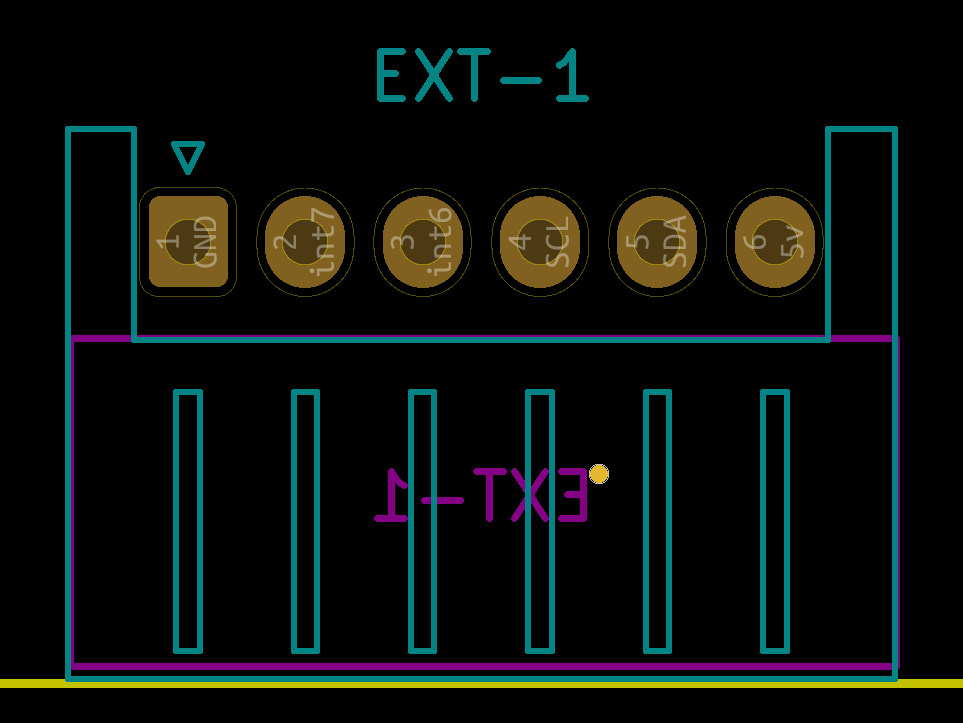
The V5 expose 2 free RBPi GPIO in the control board’s EXT connector. First V5 have the connector soldered and recent V5.1 don’t, but soldering is trivial. It’s a 6-pin thru hole JST connector. The connector also include 5V, GND and I2c pins, so you could add up to 2 extra MCP23017 chips (2x16 GPIO).
If you want to use one of this RBPi GPIO for a switch pedal, let me know and i will modify.the wiring layout to allow this use. It should be trivial
If the connector is not already soldered to the PCB then you can chose any 0.1" pitch connector to use. If it is already soldered then you can look at what is there.
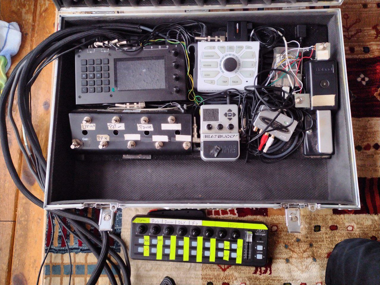
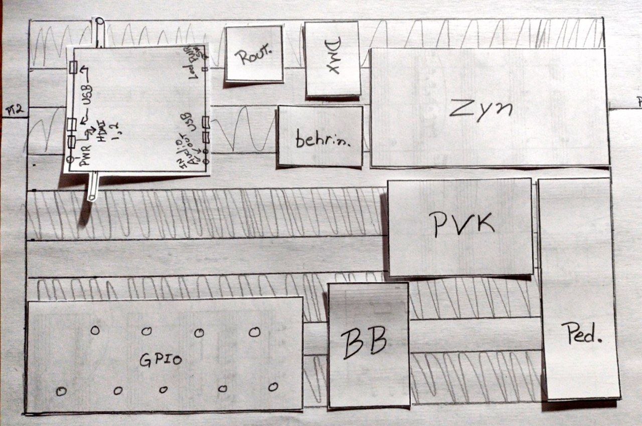
I’m in the process of totally revamping it mainly moving from this 24"x12" pedal board to a 24"x16". The raspberry pi (on the top right) hosts most of my setup (SuperCollider based) with all GPIO plugged directly into it. This pi will be replaced by a tiny (yet bigger) industrial computer with only 8 GPIO inside when I currently need 12. Anywho, the setup should look like this :
The idea of endowing the Zynthian with 16 GPIO directly inside is quite the dream. I would then need for the Zyn to have a GPIO → OSC service which should be trivial to implement. (I’m assuming the Zynthian to be of the systemd persuasion (am-I right ?)).
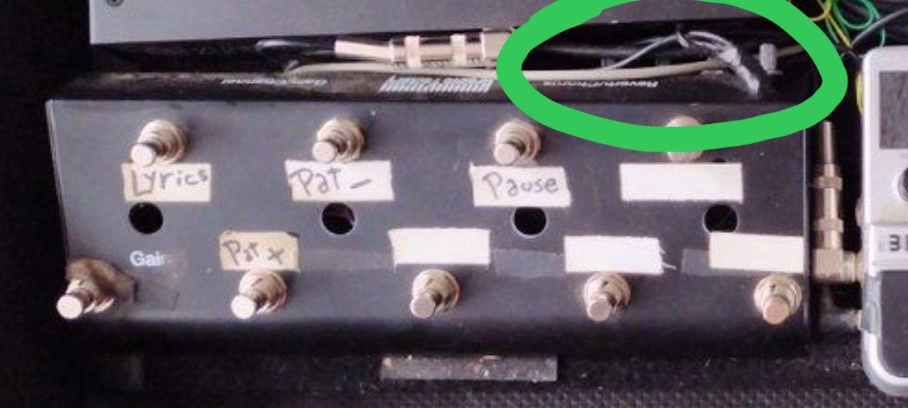
I’ve yet to fiddle around with the Zynthian as I prefer to leave it intact. Besides, the Zynthian is way too pretty for me to disfigure it. My fat fingers lack either the gentle or delicate cycle. For now I’ve only done my shenanigans with my own DIY stuff. But with that being said : I’m up for a little slit in the front for [VCC, GND, SCL, SDA] .
I’ll probably use a PCF8575 because that’s what I’ve found in my IC-mishmash box (it’s a 16 GPIO→I2C). I would install it not inside the Zyn itself but rather inside this franken-GPIO-box :
^ BTW, this box also hosts a 4 channel stereo mixer that outputs in a headphone amplifier for my in-ears (mainly for the click). Highlighted in green : the four channel-level potentiometers (no master).
I tried to characterize the interior of the female connector which should correspond to the male connector specifications. 15mm wide × 4mm high. There is 2.54mm between each pin and there are 6 of them.
My tester reported (from left to right facing an assembled Zynthian) : [GND, GPIO24, GPIO23, SCL, SDA, 5VDC]
This sounds about right to me so I’ll continue.