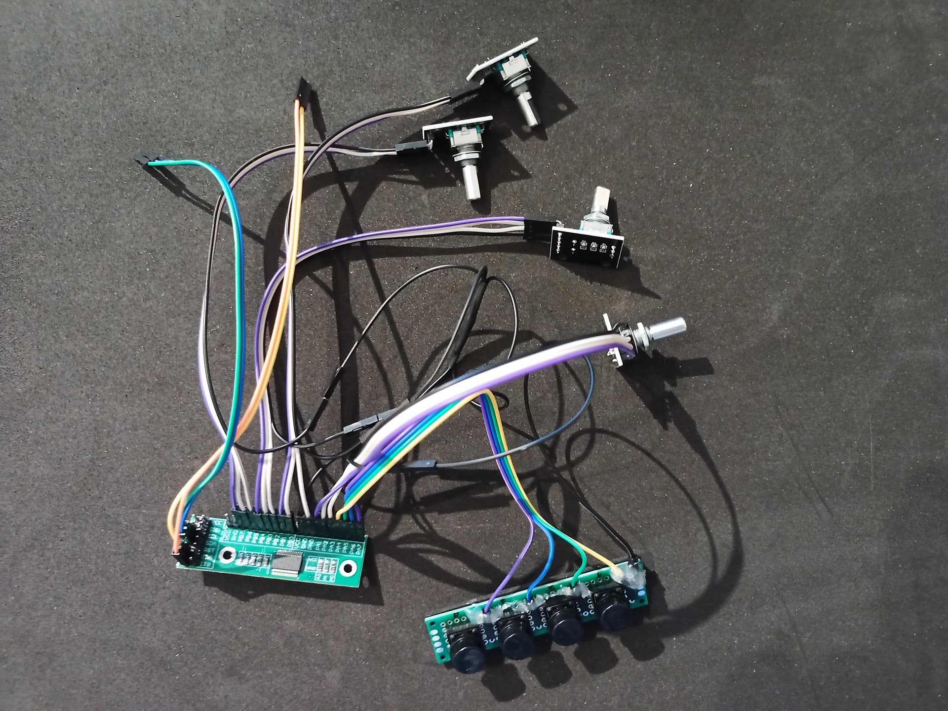
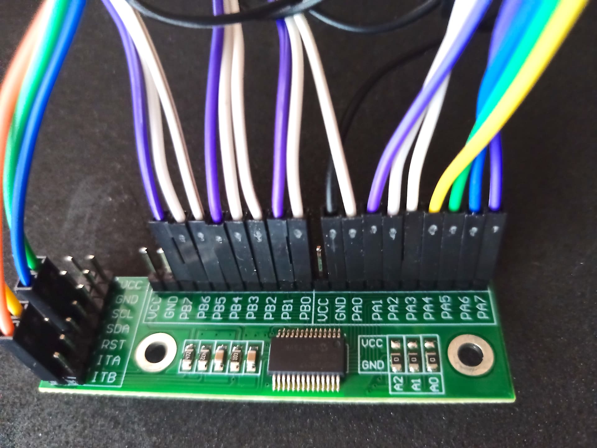
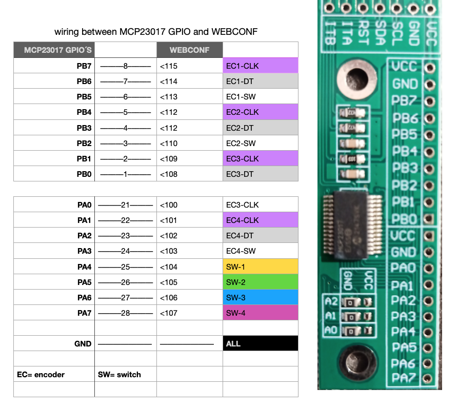
I made some progress as you can see in the attached images (1-3).
All the wire controls from A_1 to A_4; B_1 to B-4 and S_1 to S_4, are connected as the diagram (3) shows, inspired on zynthian–allinone.sch.pdf .
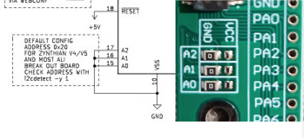
But now I am facing a new issue: please, observe the “default config detail” (picture 4). In your scheme it seems that a connection to GND must be done, but, as after reaching the A2, A1 and A0 pins on pcb, I can see two column options: GND and VCC for A2, A1 and A0.
I am not aware how this has to be done, given that GND is actually bridged by an SMD component (don´t know if resistor or capacitor), so not very sure if I have to connect the bare pins under the VCC column and connect all 3, to ground as suggested.
Excuse me for asking what may be dumb questions, but my electronic baggage of knowledge is tiny compared with my music passion that is large
Hi @erasmo these 3 resistors are for configuring the I2C address of the MCP23017 device. As is, on your board, they are placed for bridging rhe 3 A0 A1 A2 pins to rhe ground wich is the default config for Zynthian.
That´s fantastic! Thank you @le51!
Your answer confirms me another supposition I was guessing, but as I told you, lots and lots of doubts were riding at my side in the process
Though, almost a month ago, I got my project working, until now I have not been able to finish it properly.
I have had several troubles trying to mount everything into the selected case. Lots of cables fighting among themselves in such a tiny space, forced me to re-route some of them and widen the space. By now almost finished…
On the other hand, a really annoying issue was detected in the very first moment: though all the buttons and encoders worked fine –I was able to assign them to my liking– the screen tactile was lost.
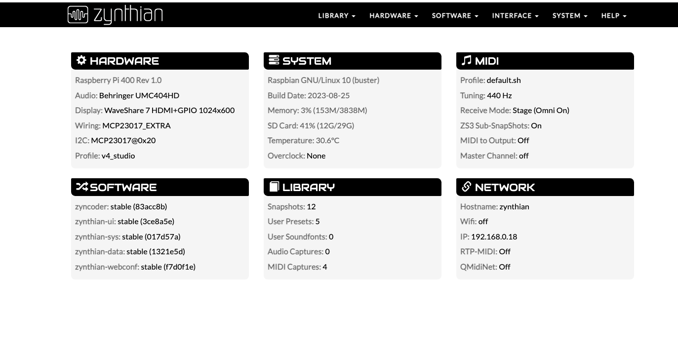
I ´ve been making all kind of connections, so in audio; display and wiring assignments, with no luck until TODAY, when I discovered a strange issue. My screen is a 7" hdmi* with micro hdmi + USB. If when ZYNTHIAN starts (please find attached screenshot of config.) I disconnect the USB screen connector that goes to raspberry, and connect it on again, the tactile comes to life!
I´m not aware of this but, may be due to a code routine of ZYNTHIAN OS that when adding encoders and buttons these get a kind of “primacy” putting USB feed on second place, or something else?
Can you advise any solution?
Best regards,
Thank you for answering so quickly as usual
I have seen the thread you linked and must to comment that some days ago I read (I think was in a raspberry thread) that under certain circumstances the screen USB driver had to be updated to make it tactile again.
I will investigate deeply. If get a solution I will post it.
Best regards,