hi, I can t find on the wiki where I can edit the custom wiring please?
i d like to use my Zynthian sequenced via midi din in, cdmi monitor and no encoders, just my midi controller, I think I have to edit something to set my midi input and told the Zynthian that there is no encoders but don t know where to edit all this!
i m a real beginner in raspberry!
thanks in advance
Do you know about the webconf?
yes I have checked it, tried about every wiring config but none of them enabled my midi din input that I have already checked around 20 times, I thought that maybe there was a file somewhere where I could edit the pins number or other things but really new to raspberry, I already built Arduino controller without problem but raspberry is so deep for me!
i also have problem using the synth, most of them don t have any sound except synth v1 and still lost between wiki, discourse and the forum, i d like to buy a full kit but I m a food truck owner her in France and so can t work because of coronavirus so can t buy the kit until I can return to work so Zynthian was a way to pass time 
so for the moment I try to make the minimal Zynthian with what I have here! a pi3b an hdmi screen, a midi keyboard a few electronic component!
Hi,
Configuring pin numbers through webconf is for the controllers, not for the midi socket.
So, if you do not get any midi in signals:
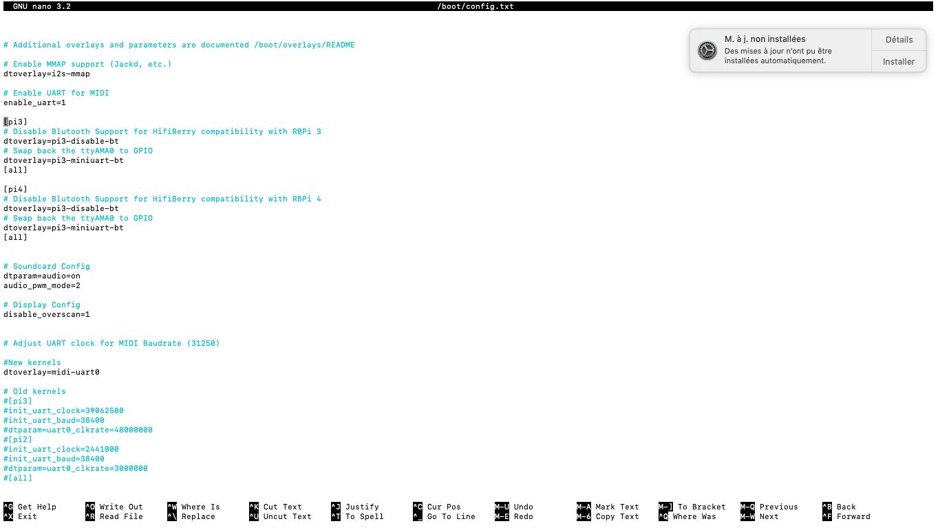
You made something wrong while soldering components ans check that in your /boot/config.txt there is a Line with enable_uart=1
1 Like
My interface is still on breadboard and checked it multi time, i think now that maybe my raspberry could have a problem, it s ûin à desk since at least 4 years and the screen show a powering problem on the top right even with an official raspberry pSU, I ll check the uart_1
Do you know what wiring setup should I use in the webconf?
Pictures can often help this sort of problem
Wiring should be set to Dummys because you have no encoders.
Provide some photos as @wyleu suggests. We may see an issue you have missed.
If you have low power indication then you could be suffering a variety of issues. Try powering the Raspberry Pi without anything connected. Disconnect all USB devices and anything connected to the 40 pin header and see if the power indication clears. If so then add each device one at a time to see which (if any) are causing that problem.
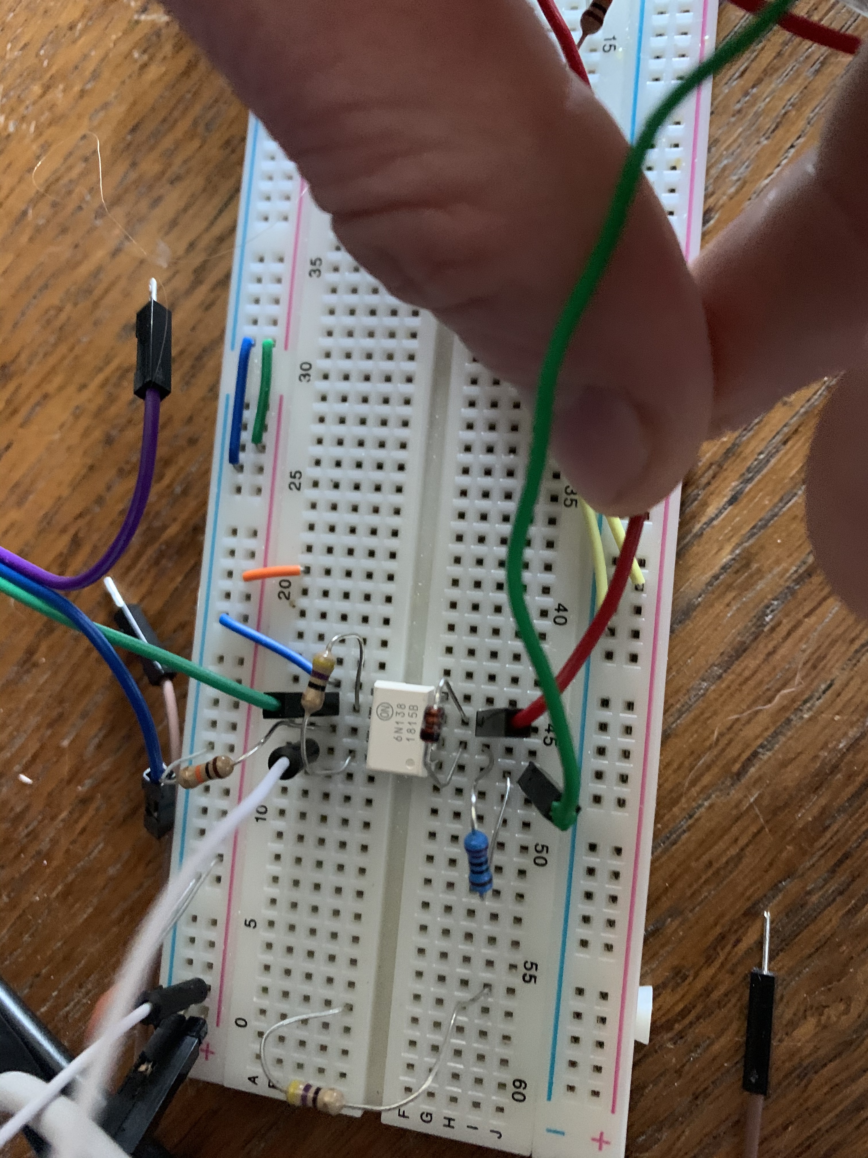
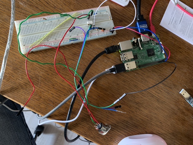
Here is the midi input gnd to pin 6 vcc to pin1
Rx to pin 10, i tried different resistor values.
Even with nothing in usb plug it show a problem!
Thanks for help guys!
It shouldn’t make a difference but I would avoid using pin 1 of the opto. It is shown as n/c in the data sheet but best to avoid connecting anything there so move your MIDI input (green wire and resistor) across one track. Probably won’t help but better safe.
Check with a diode meter that the opto diode is still working, i.e. will pass a (resistor limited) current in forward direction only. If you have an amp meter you could connect in series with the 220 ohm resistor and connect 5V–Amp meter—220R resistor–pin 2, pin 3–Gnd, then check for about 10mA. Swapping the 5V / GND should not pass any current (if the 1N4148 diode is removed - obvs).
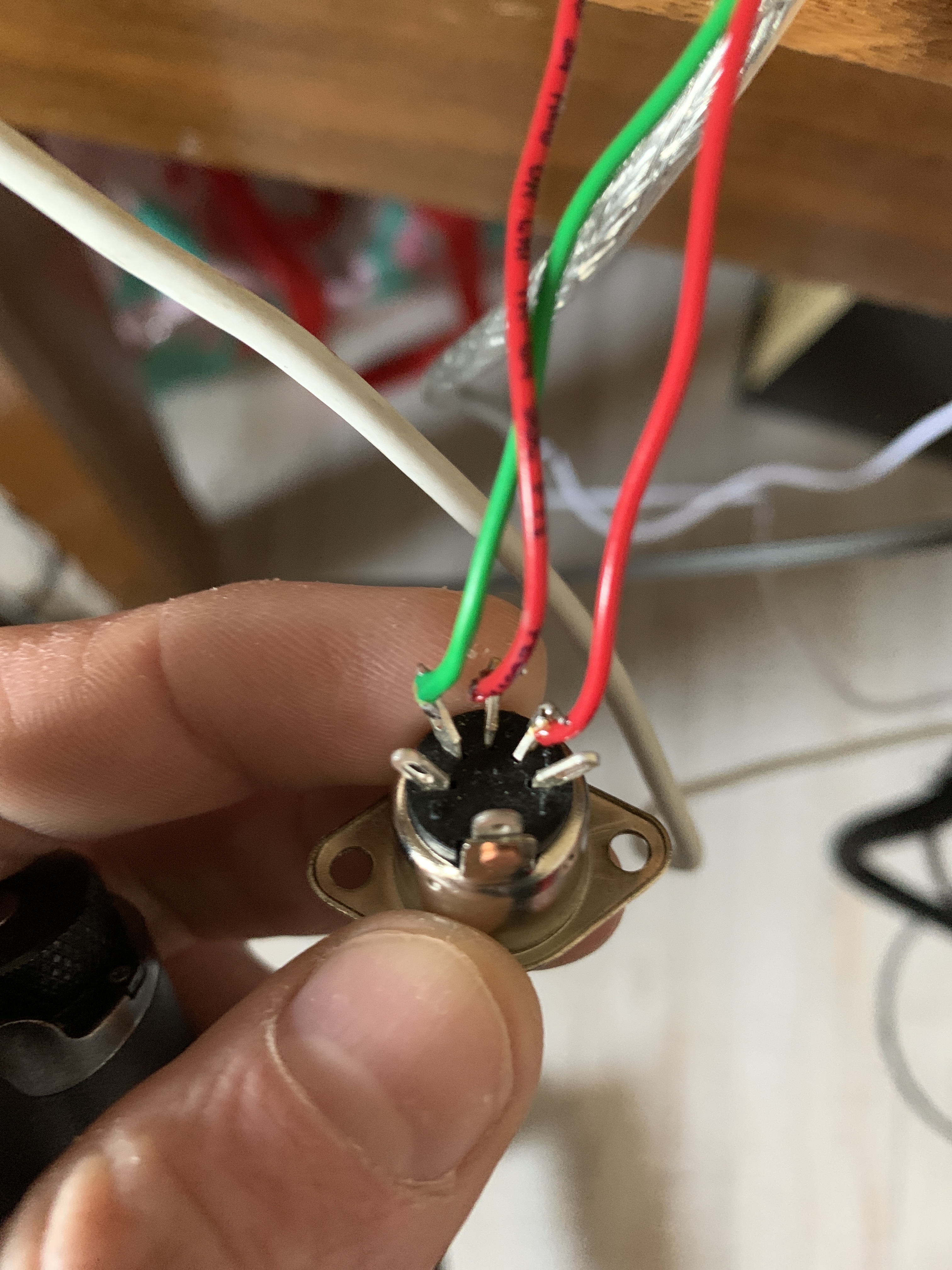
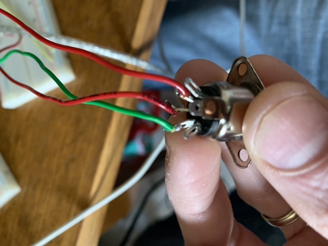
May we see the other end, i.e. picture of the RPi? Also a picture of the 5 pin DIN. Cheers
Here is my din connection (it s a 5pin that I use only for prototyping, here ground is not wired on breadboard
I already tried to swap the connectors
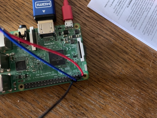
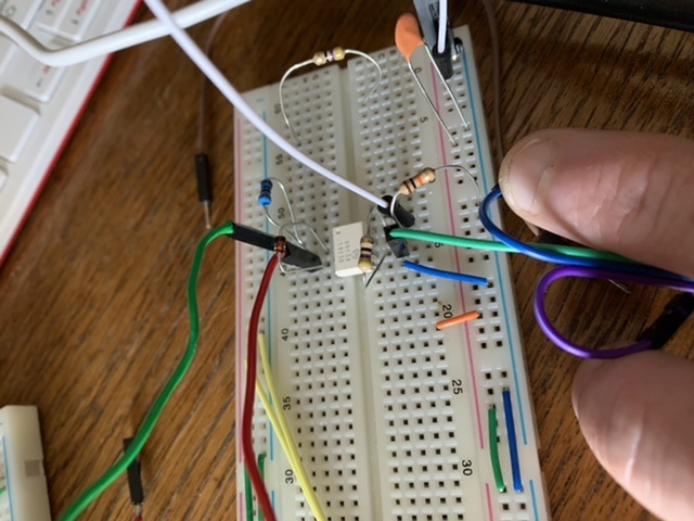
I am not sure if it is the camera angle but it looks like your black wire on the RPi is connected to pin 8 rather than pin 10.
You are right! I tried to swap rx and rx yesterday and forgot to te swap after, I just invert and still nothing!
I already also test my midi cable with other device to be sure it works fine I tried 5v and 3,3 too, really don t know what to check now!!
Also I think the MIDI is round the wrong way. Pin 4 of 5-pin DIN should go to resistor feeding pin 2 of opto but it looks like you have them the other way round. (I struggle with identifying 5-pin din pinout so may have misinterpreted but it looks wrong to me.)
i also tried swapping this many time cause I know it s one of the first mistake I made with my Arduino project but it doesn’t work in any way, I also tried with another 6n138, the 2 I have are brand new
Okay, you maybe at the stage I got to where logic failed me so I blindly followed the Zynthian Way and it worked. I implemented this circuit and all was good. It may be related to how the opto inverts the signal.
This is my working MIDI input:
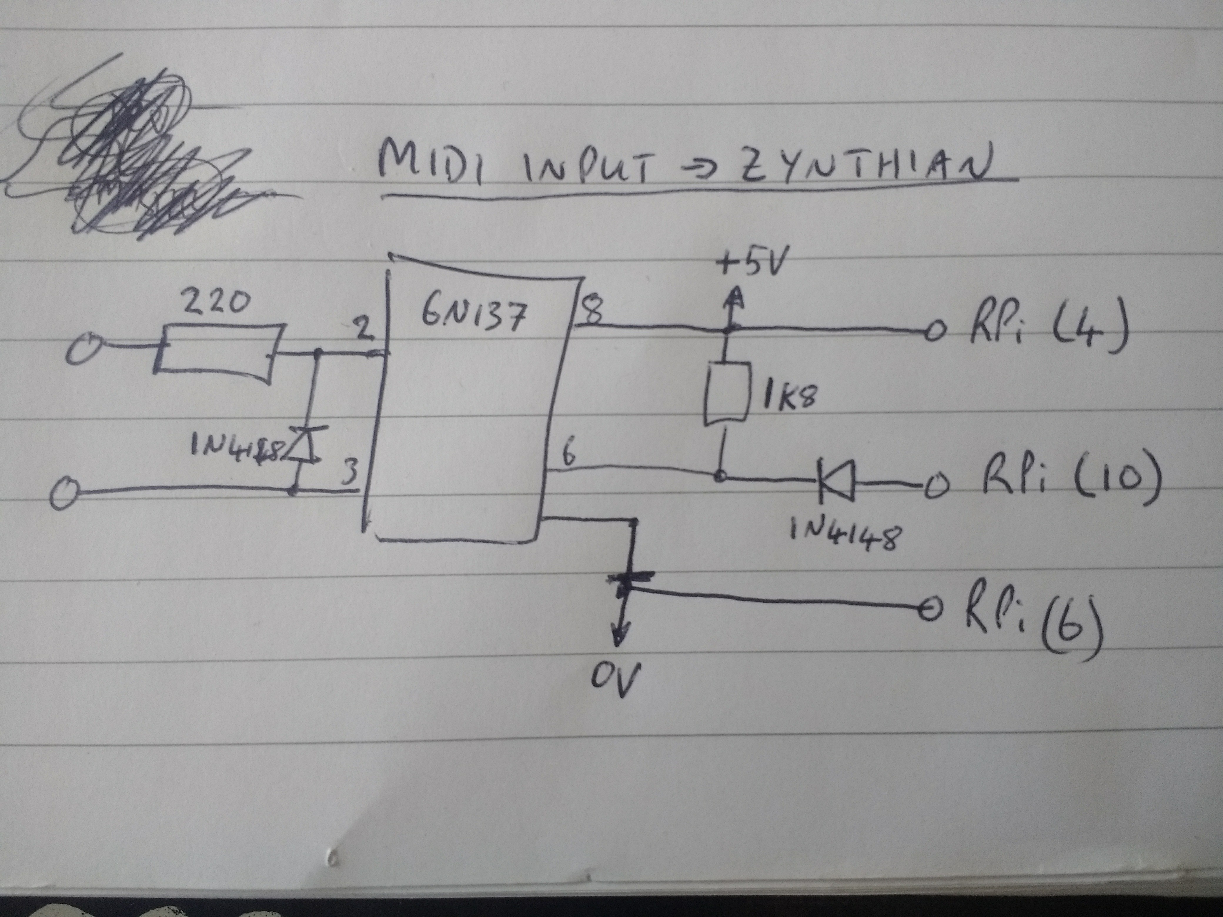
6N137 requires 5V.
RPi input supports 3.3V.
RPi pin 10 has internal pull-up.
6N137 pin 6 is pulled low to provide signal to RPi.
So this circuit provides the current loop for MIDI input, isolation to receiver, correct signal polarity and protection of 3.3V input pins on RPi.
1 Like
Thanks I ll try to add the second diode to see!!
Really thank you for help!
yes, config.txt is allright
1 Like
Also, remove the resistor from pin 7 of 6N138. Leave pin 7 not connected. And probably increase value of pull-up resistor from 470 ohms to a few kilo ohms.