Curious if anyone’s ever gutted and reused an old Yamaha Portasound - I have a PSS-170 that I just opened up and I think it’s one of those keyboard matrix thingies, I don’t have my camera but I see lots of resistors (some might be diodes, not sure) on a sparse pcb where the buttons and keys are, with some thick wires going onto the main PCB with the big brain chip and horrible FM chip.
I’m pretty certain one could attach those pieces to an arduino and use them for a Zynthian but I have not done such a thing before. Probably I’ll post some pics later, in theory I wanna make a “stealth” thing where I pull it out and people go haha toy piano and then it makes, you know, Zynthian sounds. I do love little trolls like that.
Eh, I did skim the circuit bender community a bit but they’re not actually knowledgeable, they literally just lick their finger and poke the PCB and if it sounds funny they solder a jumper wire or something. It’s more remix culture with hatchets than electronics, I doubt any of them could explain even a basic circuit (I can almost explain an RC network… almost).
Edit: Nothing against them mind you, I think they’re mad genii one and all, but not the sort of genii this task requires lol
Basically though, you can see in the pics down the thread a bit that the keys and the buttons/sliders all are on discrete boards with a relatively small number of wires crossing to the main PCB, which tells me there’s nothing especially high tech going on in there, so probably comprehensible with the right guide to resistor matrices or something. I’m rearranging the garage today but once I’ve got the soldering station setup again I’m gonna start poking at it.
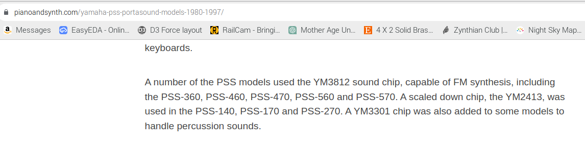
It has also occurred to me after reading the circuit benders’ page on it that the actual FM chip on there is extremely chopped and basic with very few pins, and the datasheet is available, so probably I could read that over and figure out how to just harvest the note data, possibly by soldering on some leech wires to the traces that send it to the synth chip.
One of the two will surely work, just not sure which is likely to be the lower effort of the two. I probably will go post in the circuit bender forum too, but the people who do the tutorials and stuff don’t seem to be especially geeky, just creative and willing, which goes quite a long way as it turns out.
Reverse modding stuff like this is difficult without understanding the motivation of the manufacturer in their design (normally cost, but not always)
There might well be a suitable library out there for arduino or Pico that will handle a scanned keyboard. It’s a good idea to establish if there are diodes ther ( a multimeter should tell you).
Photo’s are good because you can draw all over a print out of them and makes notes.
But you are really after a schematic to decide how to parasite onto the dat as it is.
Generally I’ve built from scratch, just using the keyboard contacts as they are. . .
I’ve got an Alpha Juno 2 somewhere that is an interesting demonstrating how wrong this can all go.
IF you just want MIDI, it’s possibly, on a pin in there somewhere already, and that would seem the quickest path.
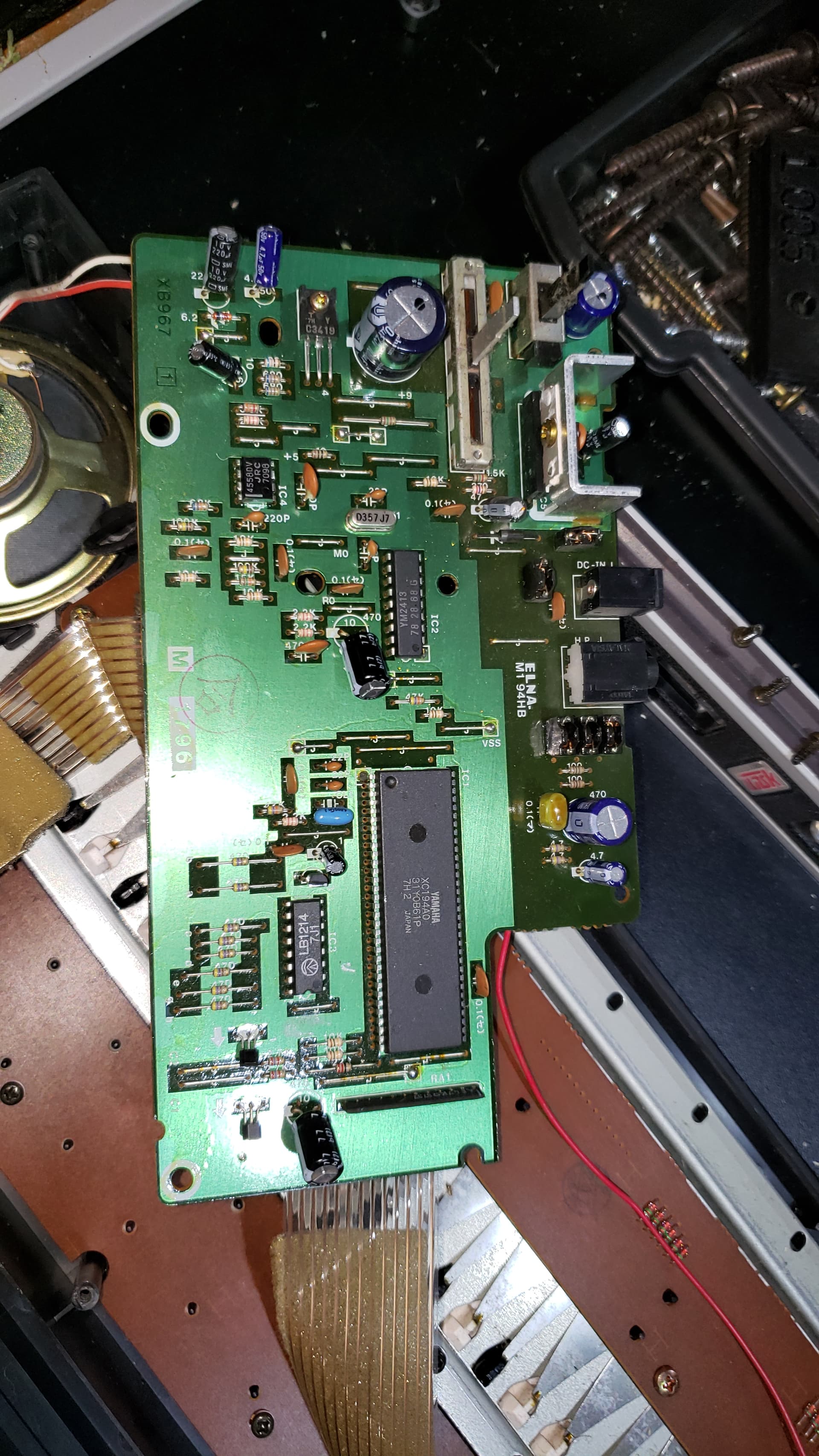
I haven’t gotten into the brain chip yet but I found the datasheet for the FM chip and while I’ve never done reading of registers, let alone tapping into bare contacts or any such, I do think I understand what’s going on in terms of how the notes are getting in, from there it’s just a lot of grinding, really…
But that’s a big brain chip and many of these Portasound units did have midi, so you actually might onto something there, at the scales Yamaha works at it would make a lot more sense to produce one chip with all the stuff. I’ll have to try and dig up the sheet for that first.
edit: the Giant chip is the brain, the little tiny one above it is the FM synth. Not sure what that other one is yet.
edit2: a General Purpose Transistor Array. You always need more transistors.
I don’t want to spoil your fun, but there is a 26 page service manual available from Yamaha via: YAMAHA PORTATONE PSR-170 SERVICE MANUAL Pdf Download | ManualsLib don’t be distracted by the ads, you have to choose the “Download this manual”(Download Yamaha PORTATONE PSR-170 Service Manual | ManualsLib) in the upper left corner of the manual itself.
CONTENTS
SPECIFICATIONS … 3
PANEL LAYOUT … 4
BLOCK DIAGRAM … 5
CIRCUIT BOARD LAYOUT & WIRING … 6
DISASSEMBLY PROCEDURE … 7
LSI PIN DESCRIPTION … 10
IC BLOCK DIAGRAM … 11
CIRCUIT BOARDS … 12
TEST PROGRAM … 15
MIDI IMPLEMENTATION CHART … 17
OVERALL CIRCUIT DIAGRAM
PARTS LIST
ah, it was too easy - but I do wonder if the right one is available, either from a web site in general or even from Yamaha itself, perhaps for a negotiable token of your esteem.
Possibly. I also can’t seem to find jack on that big brain chip. I suspect Wyleu is correct about it having midi onboard.
I also, though, been looking at the keys and thinking that probably it’s overall easier to just interface the mechanisms directly. I’ve opened up a few more recent toy keyboards in the past and the circuit was sufficiently engineered that that would not be possible, but this one it’s all actually laid up pretty clear.