I seem to remember, that it works 'backward’s in that the LED is on when there isn’t a signal on the line but it’s all inverted anyway cos it’s Open Collector, but my memory is not to trusted.
The LED’s, I believe, are connected between pins 1 & 2, with no external resistors ( a characteristic of the early days ), with the LED
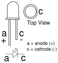
So the anode of the LED goes to pin 1 (+5V) and the current flows from (cathode) into pin 2 which if it’s a ground will energise the LED. A closure of the open collector will toggle that accordingly.
The circuits are derived from best practise in the bit bending MIDI community and seem to work in any of the examples I’ve played with but I’ve not actually handled the Zynaptik card, so I can’t be completely sure.