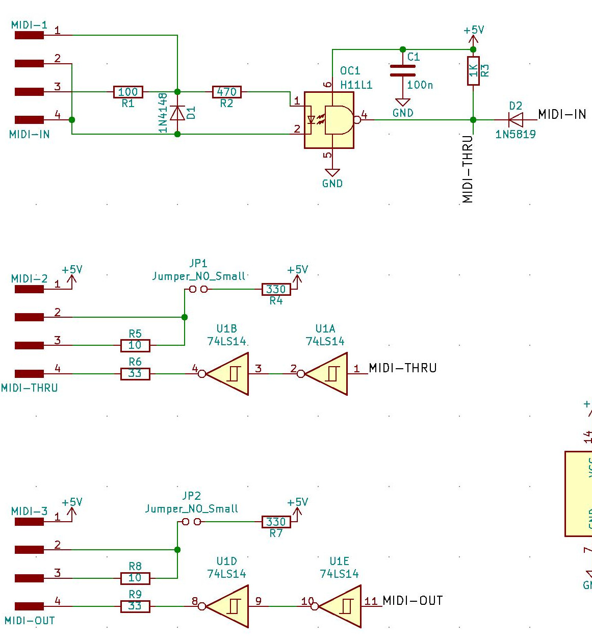
I’m trying to build a Zynthian, incorporating the bare Zynaptik PCB. I’m reading the schematic, and have trouble understanding the design behind the MIDI status LEDs. Each of (in, out, through) goes to a 4-pin connector.
I’m assuming (looking at wiki photographs) that 2 pins of each connector go to a status LED, and 2 go to the actual MIDI port. But what should be the pinout? Especially for OUT and THRU, I have trouble understanding how an LED would light up with the OUT signal, as only pin 4 would be driven with the MIDI signal. Same with THRU.
Thanks for the link! That link is to the “old” all-in-one though, where both the LED and the actual MIDI out(s) are driven from, in that case, an Optocoupler.
In the Zynaptik, MIDI out and thru are driven from a double inverter (unsure why that was changed), and the LED seems to be no longer connected to the inverter’s output. At least that’s what the schematic looks like. MIDI IN is the same; OUT and THRU are different.
I seem to remember, that it works 'backward’s in that the LED is on when there isn’t a signal on the line but it’s all inverted anyway cos it’s Open Collector, but my memory is not to trusted.
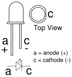
The LED’s, I believe, are connected between pins 1 & 2, with no external resistors ( a characteristic of the early days ), with the LED
So the anode of the LED goes to pin 1 (+5V) and the current flows from (cathode) into pin 2 which if it’s a ground will energise the LED. A closure of the open collector will toggle that accordingly.
The circuits are derived from best practise in the bit bending MIDI community and seem to work in any of the examples I’ve played with but I’ve not actually handled the Zynaptik card, so I can’t be completely sure.
Now I see the “loop” as well: current goes from +5V (pin 1) through the LED, back into pin 2, through the 10 Ohm resistor, out into pin 3, to the other MIDI device, back into pin 4, which will be ground when the inverter pulls it low. Makes sense!
Should I add a few annotations to the schematic for this?
Probably not, it’s like code documentation,it needs to be emphatic.
It, perhaps, might be written up, in the wiki but it’s not (strictly) a zynthian issue, more how it’s implemented in particular anointed versions in our history.
However, you could provide a small contribution for the posterity of our community !! . . . .
What would’ve helped me, was documentation of what the 1…4 pins of the MIDI connectors are connected to. I don’t mind putting that either place: schematic or wiki. Where would be the best place for it?
Sorry, perhaps My overly jocular style may be confusing…
Probably best not to alter the schematics but we would like a sound sample of the zynth you have constructed that’s the meaning of the on this forum. . . .
You have to connect the LED to pins 1 & 2, and the MIDI current loop to 3 & 4. You can take a look to the v2 building tutorial, that include details about MIDI wiring:
(MIDI wiring has not changed from v2 to v3 kits, only connectors are different)
Regarding the electronic details, you have to realize that the activity LEDs use the current from the MIDI loop, being a “true” activity LED. So:
When the MIDI loop is open (i mean the MIDI cable is not correctly connected on both sides/devices) , you wont see any light.
When you see the LED blinking, it means there are some MIDI bits effectively flowing from sender to receiver, being both sides correctly connected according to MIDI specs (1).
In other words, the zynthian activity LED act as “MIDI loop” tester. If you have connected both sides and don’t see the LED blinking, this would mean that:
The cable is broken
Malfunction in the other device (connector or worst)
(1) As MIDI specs don’t say nothing about activity LEDs, I’ve adjusted the recommended R values for having a current loop very similar to the specs. For MIDI OUT & THRU, If you don’t want to use the LED, you MUST close the jumpers JP1 & JP2, and you will get 100% compliant MIDI circuits.
I tested the circuit with several devices and it worked perfectly with all of them … anyway, if you have problems with some devices, you could try to close JP1 & JP2.
Thanks so much for the detailed explanation! It all makes sense now. And yes, it’s a brilliant idea to put the LED in the “loop” like that, since you’re testing the actual connection that way. Really nice!
And sure, I’ll hit record next time I do some Zynthian jamming
A little update: I got it working just fine. However, something got reversed between the MIDI pins 4 and 5. On the v2 wiki it says:
* JST Black (3) => pin 5 of MIDI connector
* JST Red (4) => pin 4 of MIDI connector
However, MIDI pin 5 is ground/minus while 4 is plus. For the MIDI IN circuit, JST connector pin 4 is actually connected to the minus of the Optocoupler’s diode, so that had to go to MIDI pin 5, not 4.
Or, my linked image of which are MIDI pins 4 and 5 is wrong … however, the image does match the MIDI pinout on the wiki.
Either way, very happy to have MIDI in now (and the zynscreen/cable/hifiberry all worked fine out of the box, thanks everyone!).

 on this forum. . . .