I’m working on my official 4.4 kit and looking to make use of both audio channels. Just realizing that there seems to be something weird going on with the left output channel.
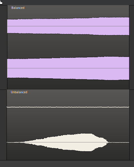
I typically use a balanced TRS cable to connect to a mixer, but when using both L and R channels, the right channel is consistently hotter than the left. When I listen through an unbalanced connection, the left channel is completely dead. I fed both into my audio interface, and did a sine wave generator test. I gradually raised the master output volume on both channels from 0 to 100. Here’s what I saw in Ardour:
Have you checked the Audio Levels page in Zynthian main UI? Digital Left and Digital Right should be at the same value to give balanced output.
I have just noticed that the PGA gain on mine is different (Left: 12.0 dB, Right: 37.0 dB). I’m not sure if that affects input or output (it looks to be with the output controls) but I don’t recall changing it so it may be similar for you. I am not at home to be able to listen to / measure the output level. (I am accessing the unit remotely via ssh.) By default the PGA gain is hidden from the Audio Levels page (and probably should be). They can be adjusted in the advanced view of webconf Audio (Mixer controls).
Thanks for the tip. The Digital Left and Right knobs are what I used to sweep from 0 to 100 and generate the comparison data in my post. I find that when the output levels are matching there’s a difference of about 7dB in the signal level (L is 7 dB lower than R), and in order to achieve matching signal levels, I need to set the Digital Right to a level about 20 less than Digital Left.
I checked my PGA gain levels and they were close but slightly off (PGA left: -1.5dB, PGA Right: -0.5dB). Unfortunately when I adjusted them it made no impact on the audio signal coming through the balanced outputs jacks.
What happens if you swap the L/R plugs over. Swapping the cables at the Zynthian end will identify if there is a cable or plug issue.
Your description sounds like you have lost or grounded one pole of the balanced output. I’m not sure if that can be configured, e.g. with jumpers. The inputs can be configured by the driver but I don’t see similar for outputs.
Swapping the L and R output cables puts the weak signal on the other channel. Swapping both ends yields the same result as the original test. So not a cable issue.
If one pole of the balanced output were lost or grounded, would that cause the signal to disappear completely with an unbalanced (TS) cable? I’m guessing it would have to be the signal to the tip that is lost, otherwise something would still come through a TS cable connection.
Do you have a multimeter? If so, remove power from the Zynthian and plug in a TRS cable to the left output then measure resistance between T-S, then R-S on the jack at the free end of the cable. Repeat for the right output using the same cable and compare the results. You should have comparable T-S readings for both outputs and similarly comparable readings for R-S for both outputs.
Are there any jumpers on the audio board? (I am not near one this week to check.)
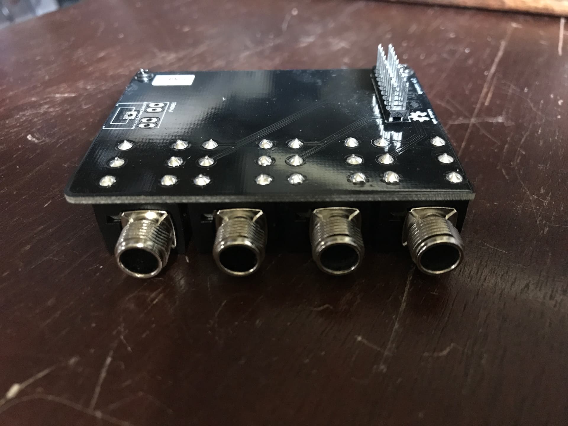
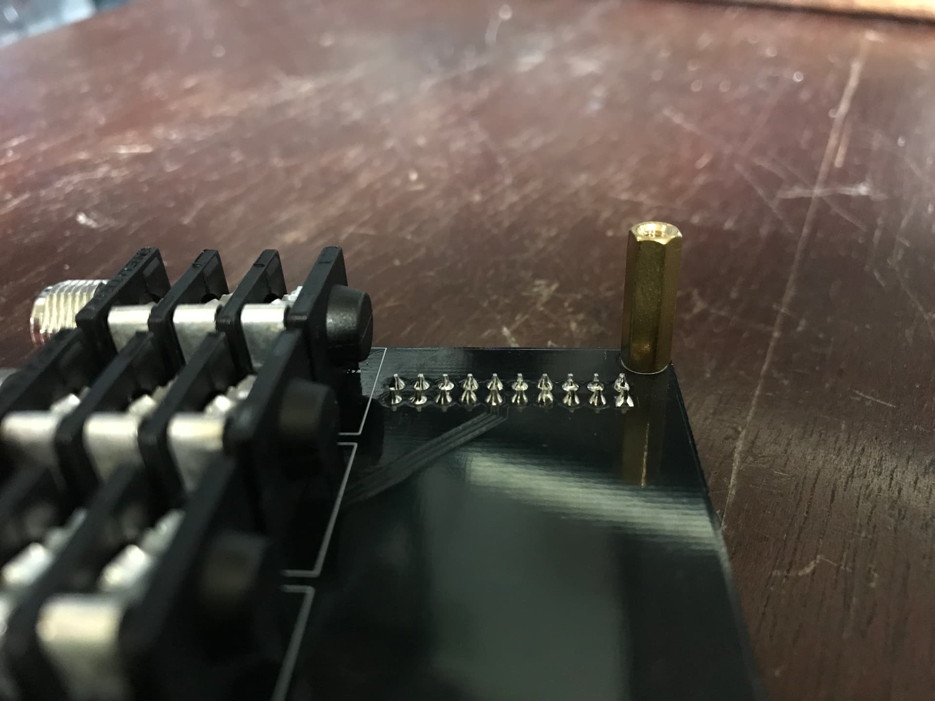
[Edit] I remembered I took pictures whilst constructing my V4. There are DIL pins on the soundcard. None should have any bridges. The only connection should be to the 1/4" socket board.
I assume you have the 4 x 1/4" sockets mounted on a PCB with a ribbon cable linking to the soundcard. (Early models had individual sockets on flying leads.) There could be a short circuit on that board, most likely due to a solder bridge on the DIL header to which the ribbon cable connects. Check for shorts on that connector and at the corresponding 1/4" output socket.
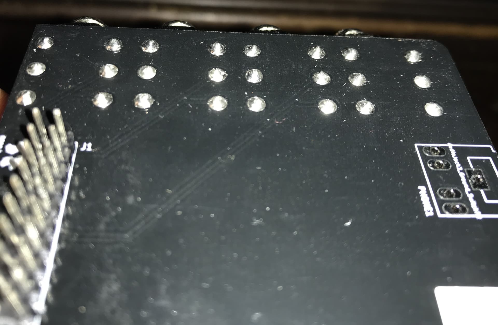
Loss of signal using a TS (mono unbalanced) cable suggests no signal on the tip (hot / + / mono) which could be caused by a short circuit to ground or by having completely missing signal, e.g. due to a dry joint. Dry joints can often be recognised as a solder joint where the solder does not form a conical shape, sometimes being a ball or sometimes there being excessive flux (red / brown material) at the joint. Check out the post with pictures (5th response) here.
So I measured the resistance at each point, here’s what I found:
Right channel (working as expected)
tip to sleeve: 7.52 ohms
ring to sleeve: 7.50 ohms
Left channel (the suspect jack)
tip to sleeve: 0.0 ohms
ring to sleeve: 4.65 ohms
Seems consistent with the dead tip signal theory, but why would the ring be reading so much lower than the other channel?
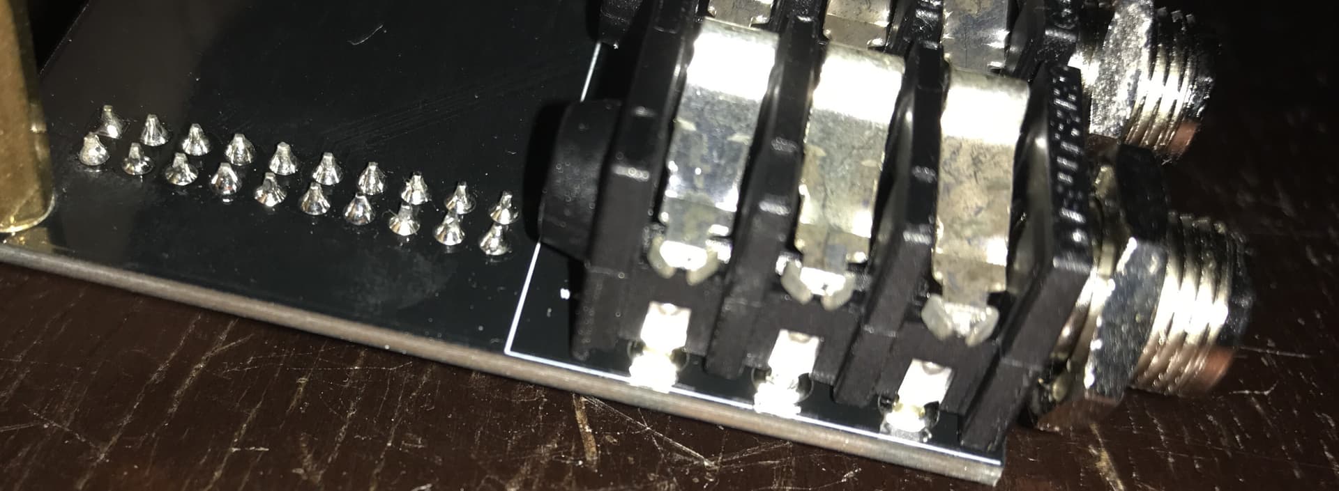
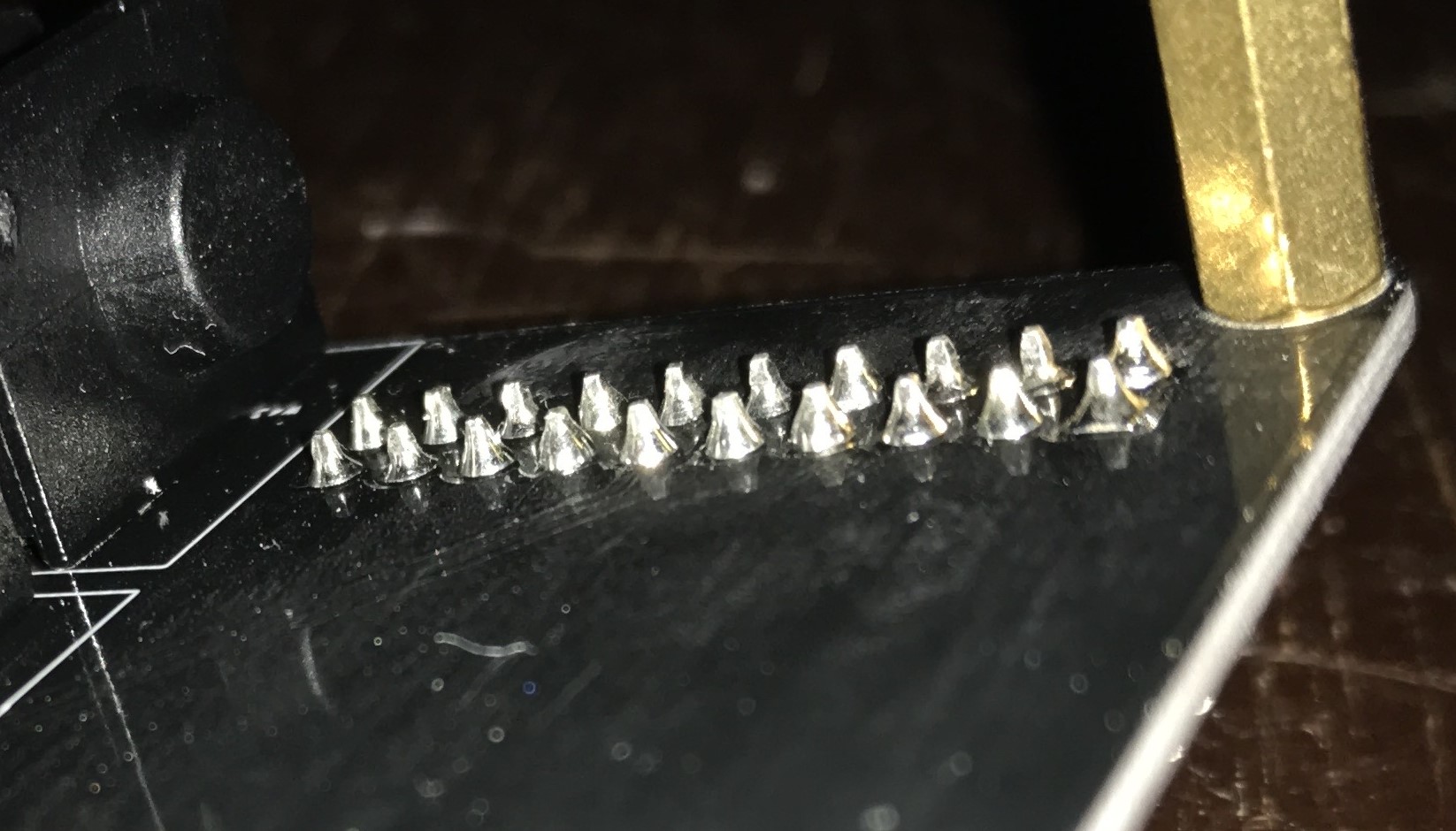
I visually inspected the solder joints, and there are a couple joints on the socket array that just might be on the verge of a cold joint as they’re more rounded on top but it’s hard for me (a noob with soldering) to say. I took photos, tried to get as clean a shot as possible:
Thanks @jofemodo, that’s definitely worth checking - do you have any suggestions for the best way to do a continuity test on a ribbon cable? My multimeter tips are too large. I have some spare jumper cables and a breadboard lying around…
The short between tip and sleeve is your issue. We need to figure out where that is happening. The likely reason for the lower impedance between ring and sleeve is because there will be some components common with the tip and ring hence the tip being shorted will impact the ring too.
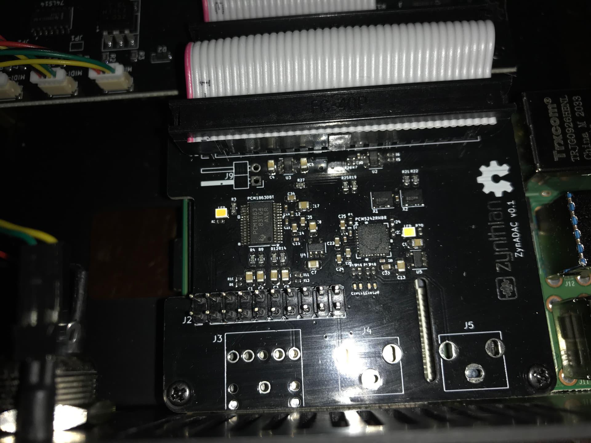
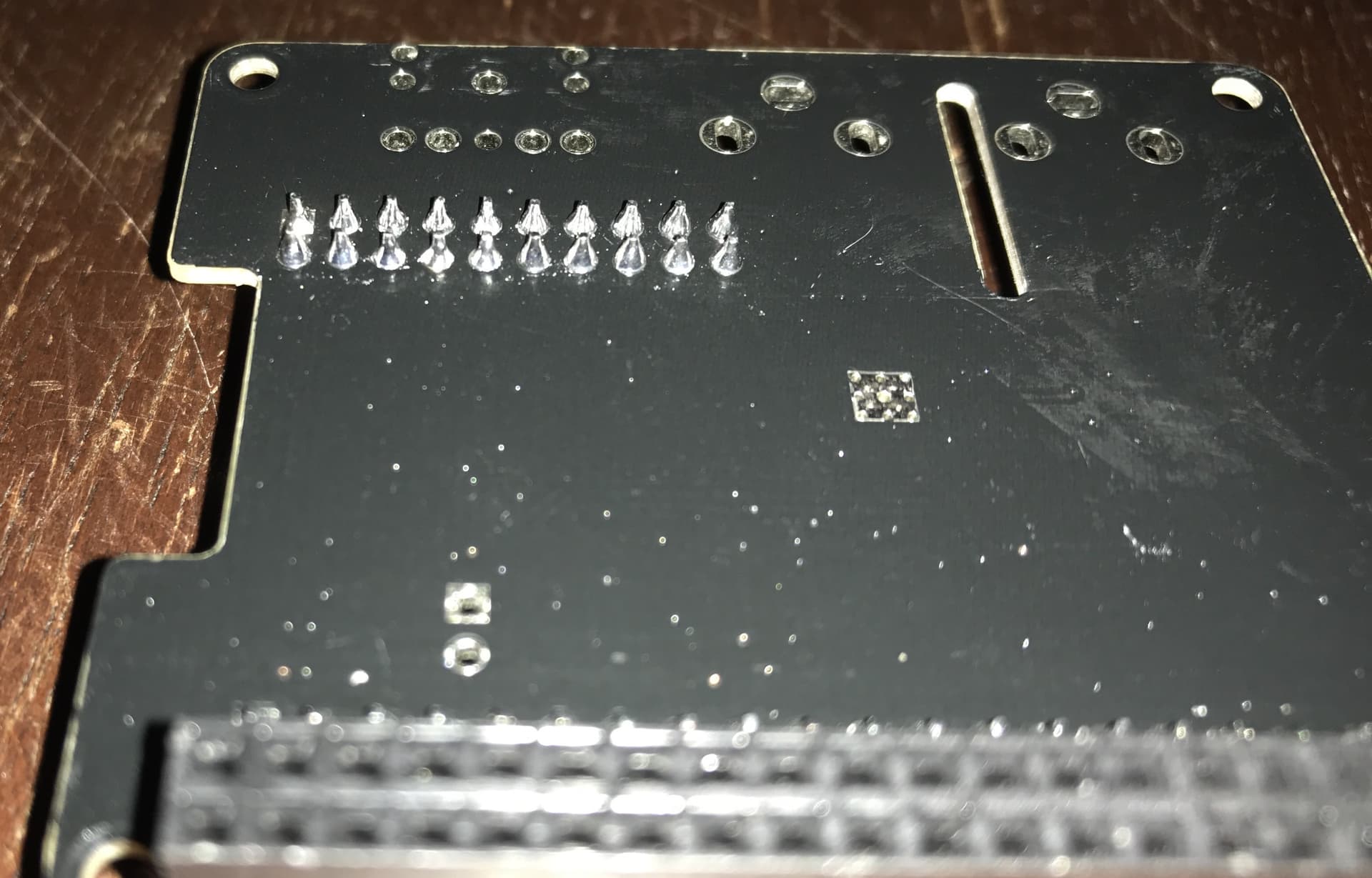
The 20-way DIL header on the audio breakout board mostly looks okay. There are a couple of pins which aren’t perfectly soldered but we are not looking for a short rather than an open circuit hence we are looking for bridges. I can’t see from the picture if any of the opposing pins are bridged. There are a couple that might be but a picture from directly above may help. Also a picture of both sides of the HiFiBerry soundcard may help diagnostics.
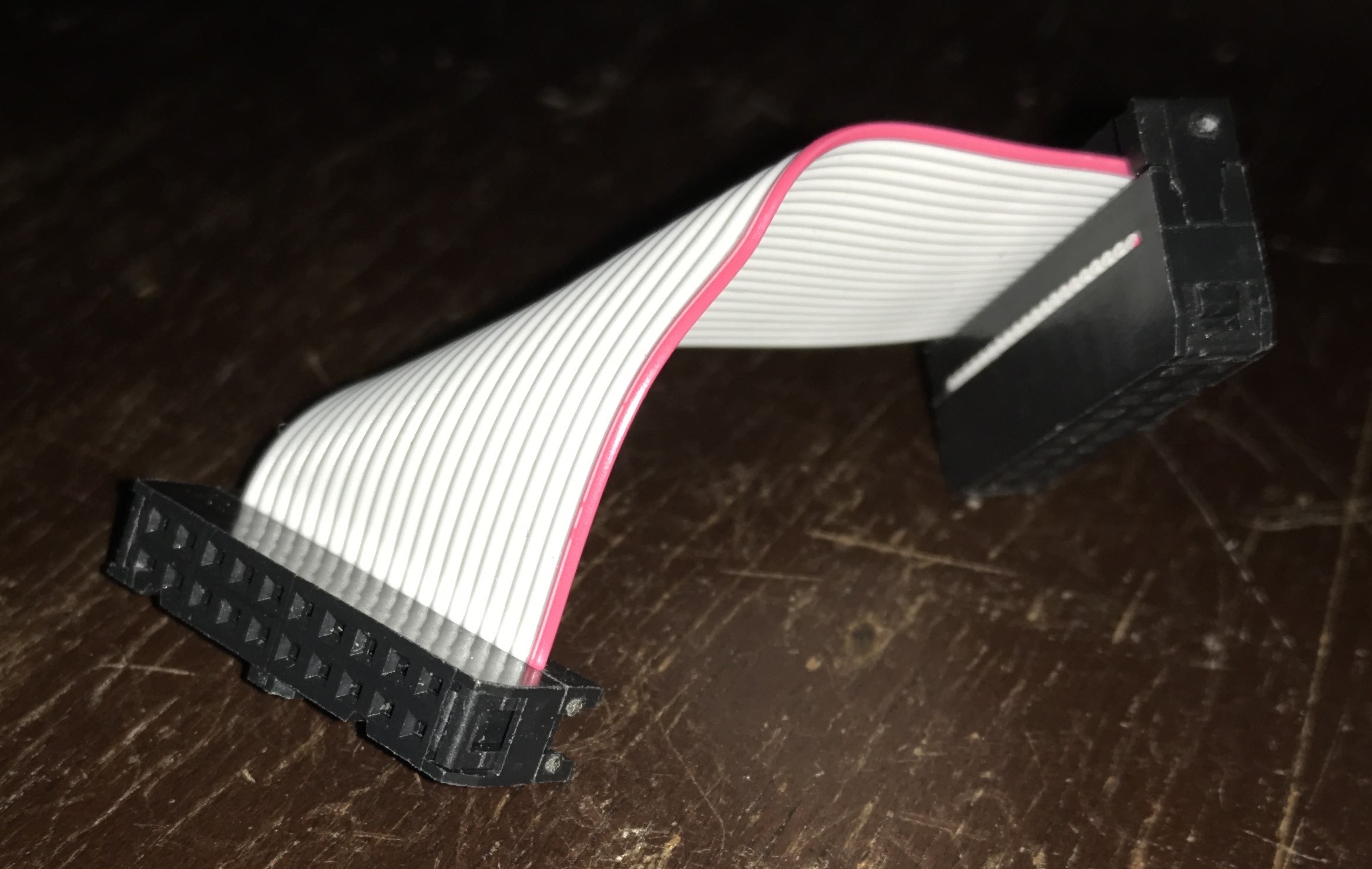
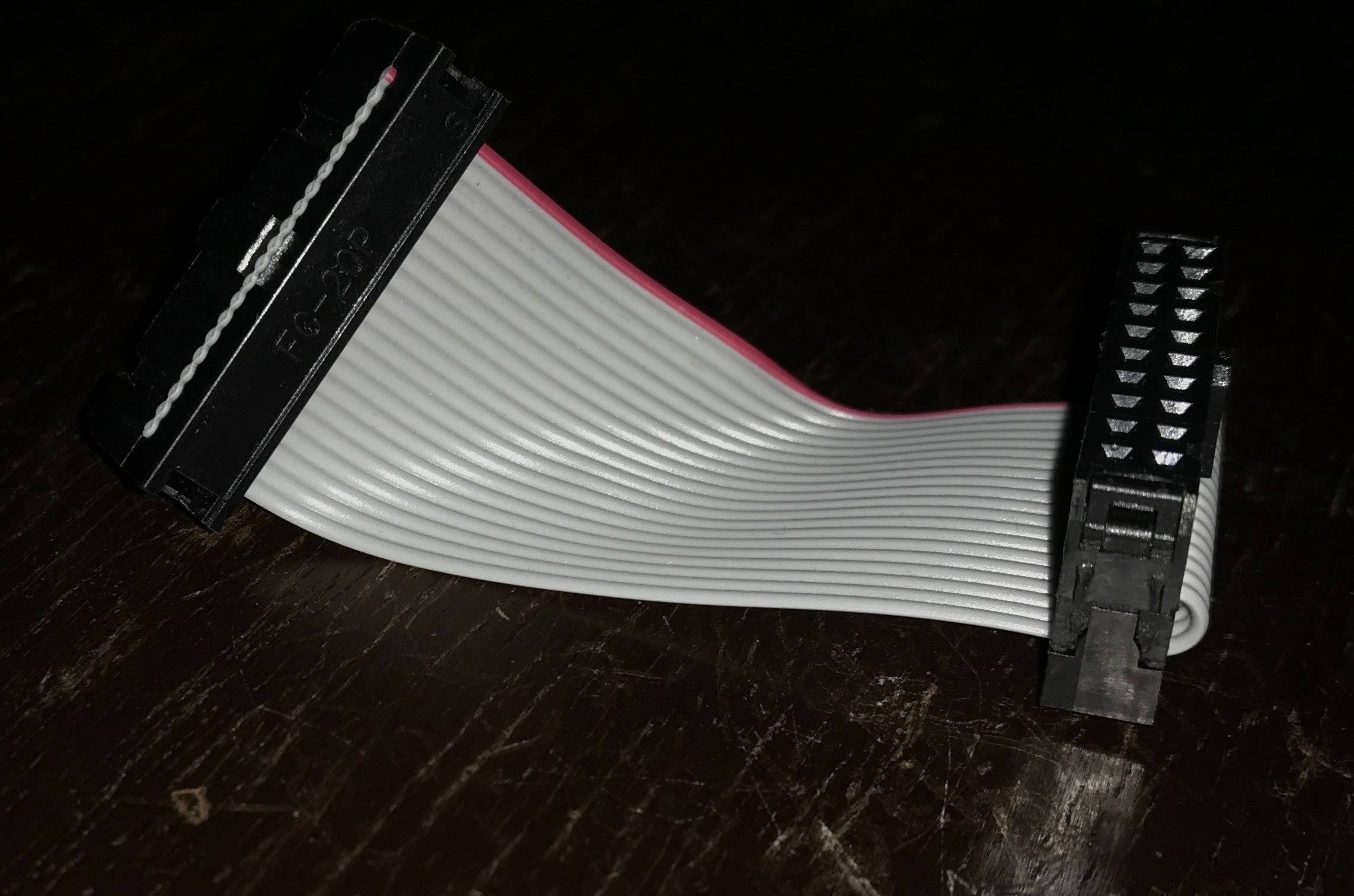
I think @jofemodo meant short (or closed) circuit, i.e. checking that adjacent pins are not connected. You can cut short bits of wire and insert them into the ends of the DIL headers to expose the connectors. I don’t think this beneficial. We are looking for short circuits which is quite rare with a ribbon cable. A visual inspection of the cable should suffice (until it is the last thing to check ). Maybe a photo of that would also be in order.
So my Zynthian components just got through quite a photo shoot.
From my (quite limited) perspective, there is nothing visually indicating a short circuit like a solder bridge. I also tested the ribbon cable (thanks for the tips, was quite easy) and it passed for continuity on all 20 wires.
I haven’t gone through a short circuit test yet on the ribbon cable as I want to verify where to focus my testing. Based on this diagram in the wiki I would be looking for a short involving pin #19, correct? (Usually the tip of a TRS balanced signal is the positive, right?)
So I should check the connectors at both ends of the cable, testing pin 19 against all the other pins to make sure they aren’t bridged internally? Please correct me if my logic is off.
I got to running a few more tests and came across something strange (to me, at least).
Every continuity test for R+, R-, L+ and L- passed all the way from the loose end of a TRS cable to the 20-pin header on the ZynADAC card. I also checked to see if the suspect L output tip showed continuity with ground at several points, and found nothing. When I checked the grounds, however, one thing stood out on the ZynAuCon board.
For both L and R output ring circuits, there is no continuity in the ground-side. The tips seem to be grounded on the pin opposite the ‘hot’ pin, and the sleeve is grounded on both sides. Forgive me if my terminology is imprecise or unclear. I checked the balanced input jacks the same way and they are both grounded as you would expect - both pins of the sleeve and the ‘cold’ side of both tip and ring. So its the input jacks that are either wired differently or perhaps malfunctioned.
Is this expected? Or could it be related to the issue I’m troubleshooting? It seems strange to me that both the L and R outputs have the same apparent wiring issue when it’s only the L output that is not performing as expected. Perhaps there’s an explanation.
One other thing I noticed, using this diagram for reference, the R/L + and R/L - were backwards from what I expected. That is, i found continuity between these points:
You are right that the pinout seems reversed but its not really that important if both outputs are phase reversed. There will always be a delay between inputs and outputs that makes such a phase difference indistinguishable.
When you measured Tip/Sleeve impedance, did you have the breakout board connected to the soundcard? (I suspect you did due to the values you posted.) Try the same measurement with the jack breakout board disconnected, i.e. just measuring to the breakout board. Then add the ribbon cable only to the breakout board, not the soundcard so just measuring the board and ribbon cable. This will show if the short circuit is on the breakout board, cable or soundcard. Also try with the soundcard connected only to the breakout board by the ribbon cable without any other connections, e.g. on the table, removed from the case. This will check if the short is being caused by other connections to the soundcard.
Yes. You are right @riban. I made a mistake when routing the board. I didn’t realized that the cable should be bended, what is the cause of the swapping, but as you set, it’s not important because both channels are reversed, so i decided to leave it like that.
Regarding the TSR connectors, input and outputs are not connected in the same way. “Normalling” is different:
As you can see in the schematic, tip & ring are normalled to ground on audio input. In other words, when no Jack is inserted in the input TSR connector, the soundcard input is connected to ground. We don’t need noise when nothing is connected.
Audio output is totally different. Tip is normalled to ground, while ring is normalled to the unbalanced stereo minijack (headphones). In your board this connector is not soldered, so ring is not normalled. In other words, when no balanced Jack is plugged in the output TSR connectors, the signal is unbalanced (tips are connected to ground). Only when a balanced Jack is plugged you get the balanced signal.
This is a bit strange, but i design it in such a way because i’m not amplifying the signal from the DAC, so there is no power for headphones and line-out. You have to choose. If you use the line-out, no headphones. If you want the headphones, you can’t use the line-out.
I know, I should add a headphones amplifier and remove this limitation. I will do in a future version, OK?
@riban this was a great suggestion to narrow things down.
I measured infinite resistance from T-S and R-S with the breakout board completely isolated. Same with just the ribbon cable attached. Not surprising as the circuits are open.
With the soundcard removed from the pi + case, connected only via the 20-pin header to the ZynAuCon, I read:
Ring to Sleeve: 4.6 Ohms
Tip to Sleeve: infinite
(Both tip and ring of the right channel read ~4.6 Ohms)
Does this mean the issue is on the soundcard? Or is it just that I only have a complete circuit when the sound card is connected?
 ). Maybe a photo of that would also be in order.
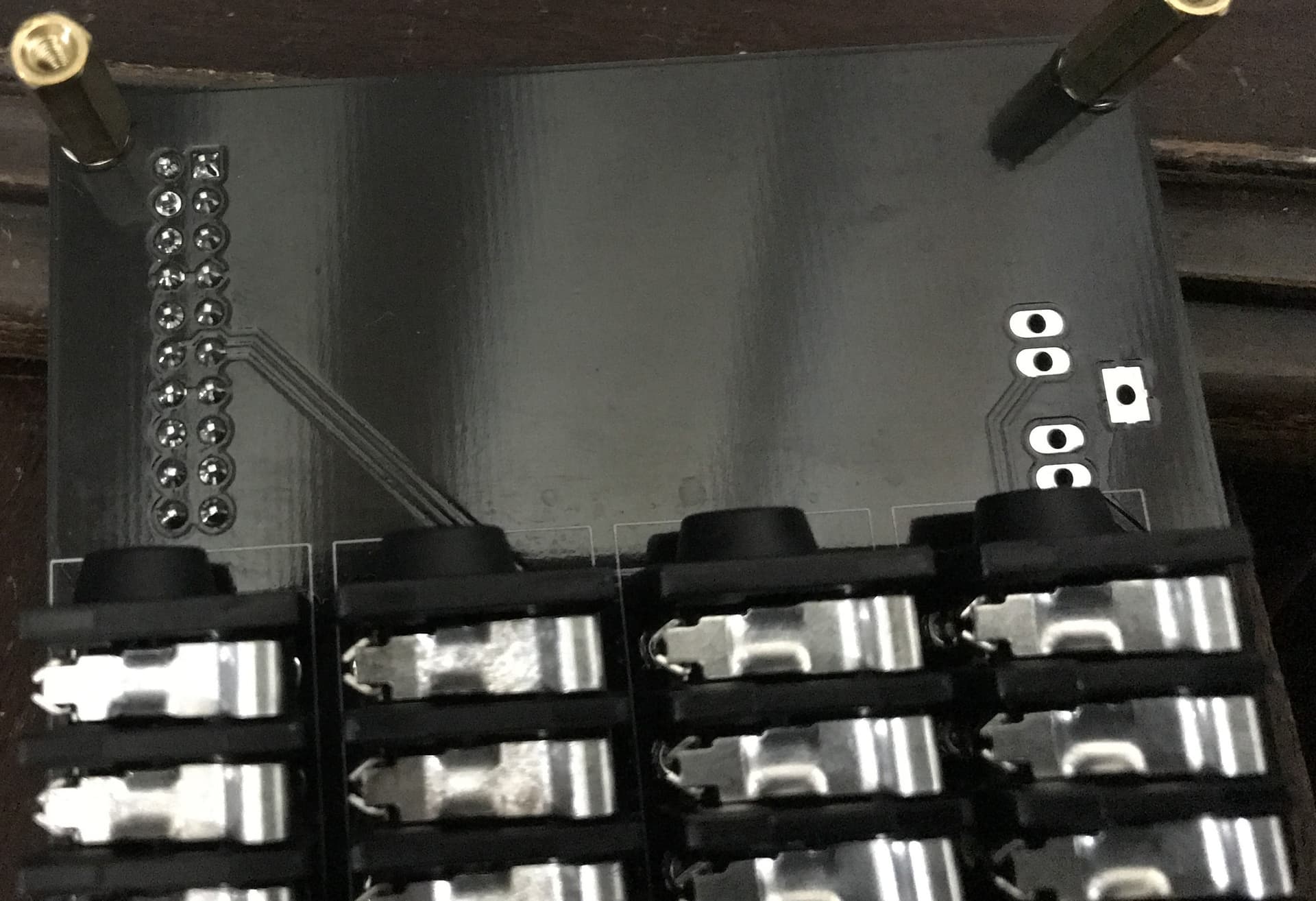

