You could look at how Zynthian did it in the github repo:
ST makes Time-of-Flight sensors and has some good doc and dev boards:
https://www.st.com/en/imaging-and-photonics-solutions/time-of-flight-sensors.html
You could look at how Zynthian did it in the github repo:
ST makes Time-of-Flight sensors and has some good doc and dev boards:
https://www.st.com/en/imaging-and-photonics-solutions/time-of-flight-sensors.html
The distance sensor is a clever little chip that does car distance sensors that sort of thing. It fires a pulse of InfraRed light and has a fast enough component to measure the time of flight.
I use one to track the pendulum on our clock.
If talks out over I2C so it’s no different from the MCP23017 from the point of connection. You just stick it on the bus in parallel with whatever elese may be there. I think they default to 0x29 but I can’t remember and it’s configurable by tying pins together on the device or something similar.
It doesn’t need an interrupt.
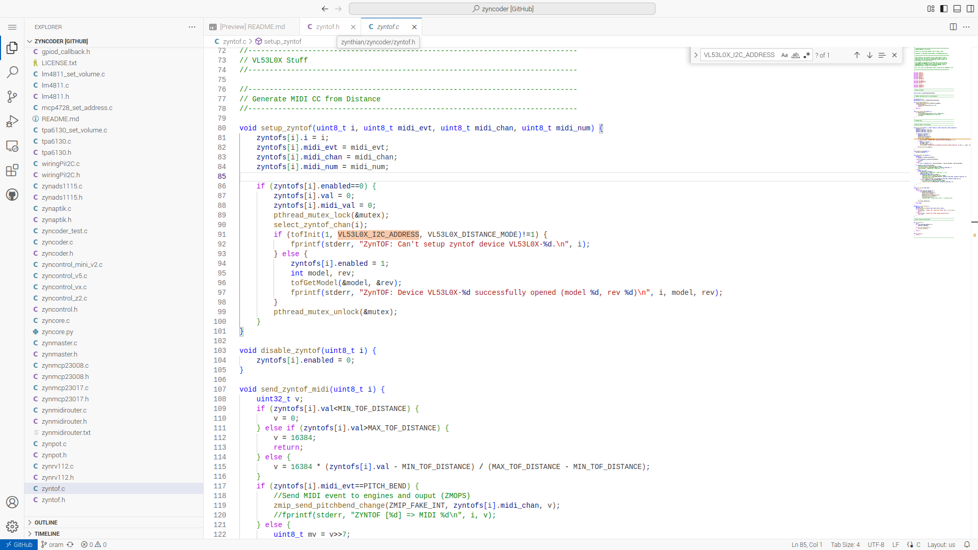
IT’s coded in C and this is the code on github . . . .
Using the . key when viewing github will bring it up in vsc, which is nice.
But how can zynthi then distinguish between two distance sensors? You’ll set two MCPs to distinguishable addresses by the adress pins between 0x20 and 0x27, but how to connect two distance sensors when they have address 0x29 by default?
EDIT: I cannot look into the schematics right now, but from the C code I suspect there is some I2C multiplexer involved. Would be interesting if I could at least wire one TOF sensor to the I2C bus without that multiplexer, since writing my own code for that seems unreachable. But I’m afraid I cannot, because the program would look at a TCA954X_I2C_ADDRESS anyway.
Indeed it appears there is . . .
Looks like a chip specifically designed to address (sic) these sorts of conflicts. . .
And quite what form of physical gymnastics the coder was considering as a use case, can only be left to the imagination!
As I read it, it needs the multiplexer chip to initialize to start polling the thread.
It can generate Pitchbend or CC depending on setting.
There’s probably more code in establishing the context is there is in actually making the change. It’s another bit of stuff in the webconf probably.
It can’t do any harm and its probably not a difficult change.
Really just a feature request away. . .
But. It might get bounced.
Most of mine do.
I have to think about that. Might be a little over my head right now. I’ll check the Zynface shematics to see if it is too complicated.
Or do you mean having only one TOF sensor statically at 0x29 would be one feature request away?
compose a feature request outlining the desire.
It’s a more formal request and tends to get treated with more consideration.
But you know, Gods are what they are. . . I’ve always wondered quite how the TOF sensor ended up as an option.
I mean, impressing the band members with some waving in the air for at least one rehearsal seems an appropriate reason for taking the challenge. But I’ll look into the schematics how it is implemented in zynface because two would be also nice.
Reading the data sheet shows that with the multiplexer you would get a maximum of 2 sensors anyway, right? So it might be interesting if there was an option to just connect 2 directly to the i2c bus and changing the address software wise.
Yeah that confused me.
One of my homespun little bits of wisdom is,
There is always a missing fact that explains it all . . .
Once you know that fact the explanations become easy because you understand the motivation for the activity.
Do you think there is a prototype out there somewhere?
I’ve got a similar sensor on my Roland A-88 keyboard. I’e never used it beyond proving it works.
What do you mean by prototype, you mean if it have been done before? Well, here, quite on top of this thread.
I’ve read but don’t always remember!
Hi,
please let me ask one question again about that topic:
I ordered some parts for expanding my custom build here, namely:
I found out the way how to connect the ADS1115 board in the schematics, but that will be a second step. I wanted to try the ToF sensor, but did not find it in the Zynface schematics. Can you tell me how to connect it to a custom build?
My guess is that it should maybe work without the multiplexer board when configured manually, but I think there is a configuration in the repo using the multiplexer because I think it is intended to use for more than one ToF sensor which may want to default to I2C adress 0x29. If connected without it may be necessary to connect V+, GND, SCL, SDA to the respective Pi pins. But I struggle with finding out how to connect to the multiplexer (and the multiplexer to the Pi).
So can anybody tell me how to connect it or give me a hint if there is any applying schematic in the repository already?