ZynFace V2

Hello Zynthian world, I have just bought a Zynthian V5 kit and am enjoying exploring the sounds and capabilities of this amazing instrument.
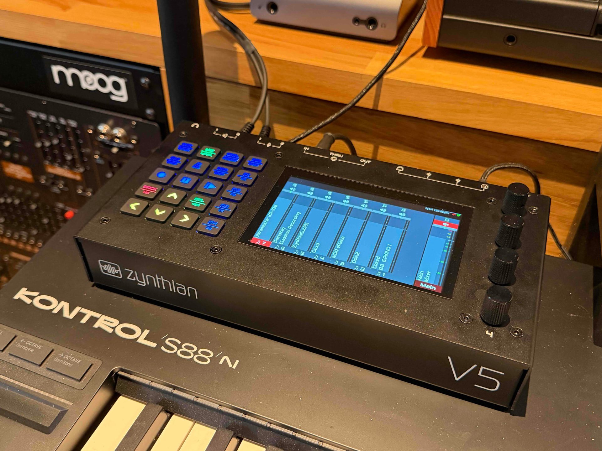
This will remain my reference unit and is connected to my MIDI keyboard and DAW (Logic Pro).

I know I am late to the party, but I have started to build a second Zynthian unit, which I intend to connect to my Eurorack, using the ZynFace circuitry.
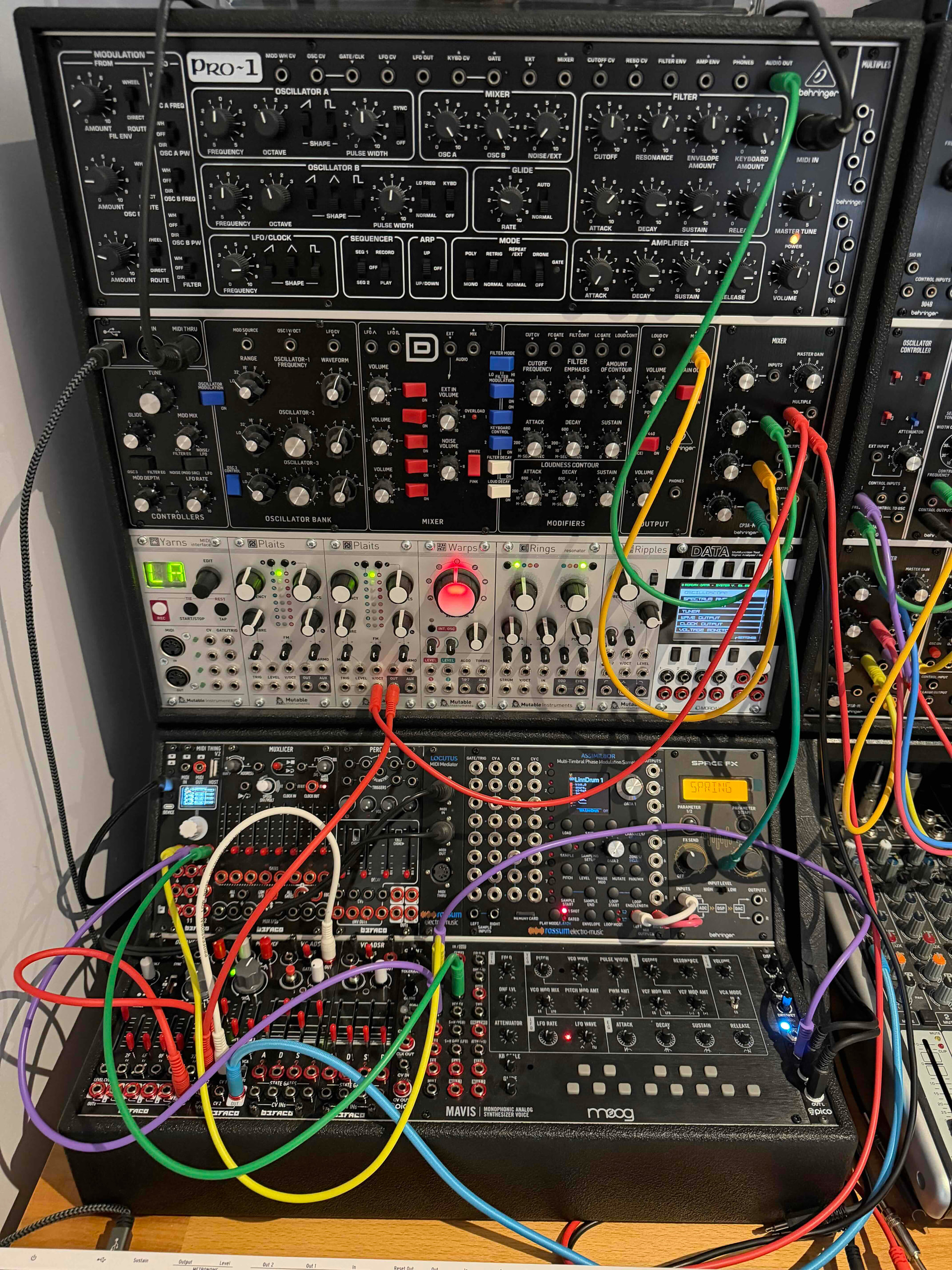
The Euroracks consist of Behringer, Mutable Instruments, Rossum Electro-music, Befaco and Moog modules. I notice from the ZynFace schematics, that the levels are 0-5V for both CV and Gate. While I am sure I can get this to work, it will be limited compared to other MIDI-CV interfaces that I use. The most capable of these is the Befaco MIDI Thing V2 … MIDI THING V2 - Befaco

They used the MCP4728 (like ZynFace) in their first version, but now use the MAX113000, which is an amazingly capable 20 port mixed signal device with integral 12-bit ADC and DAC, which can be assigned to any of the I/O with selectable voltage levels. https://www.analog.com/media/en/technical-documentation/data-sheets/max11300.pdf

Befaco have implemented 0-10V, 0-8V, 0-5V and +/- 5V in their module, which can be programmed for every one of their 12 I/Os.

I would like to propose designing a ZynFace V2, using this device. I can do the schematics, PCB layout and manufacture, but was wondering whether this SPI device could be interfaced to the existing Zynthian V5 architecture? @jofemodo does this seem feasible and would it be something the community would be interested to support. I could write a requirements specification if that helps?

3 Likes

Hi @KMcA !
Welcome on board!
Have you checked the zynface-v5 design?
It’s available in the repos.

Regards

Hi @jofemodo, thanks for the quick reply. Still finding my way around, but I did have a look at the V5 and zynface-v5 schematics. I am planning to design a single Eurorack board which includes Encoders, Audio and CV/gate circuits. I will use the ADS1115 and MCP4728 for the prototype. Will let you know how it goes. Regards KMcA

1 Like

Hi @jofemodo, forgot to say, I don’t see much user documentation on Zynface, I am assuming that selecting the Zynaptik Input/Outputs and Switches in Webconf configures the Zynface HW.

Zynthian uses I2C for its inter-module communication. We do not currently use the SPI interfaces but we also do not use the pins of GPI 9..11 which provide SPI-0. In theory you could write some code to interface with this interface and build a card that connects to these pins. I would avoid using the SPI-1 because it shares pins with the I2S channels which can be used for audio inputs and outputs.

Hi @riban, thanks for the clarification, good to know that SPI-0 is free. Might be simpler to use a microcontroller like RP2040 to setup/manage the MAX11300 and communicate with Zynthian via I2C?

1 Like

I would like to do this for all out-board interfaces. Zynthian could offload its i/o to a microcontroller, including switch, encoder, MIDI, CV, etc. I would love to see this in a future build. I did this for the first zynthian I built, using a STM32 Bluepill dev board and wrote a I2C interface. It worked really well and I see merit in revisiting this. There have been reasons why we have not done this but those can mostly now be mitigated.

2 Likes

OK, that sounds like a good plan. I have a couple of MAX11300 evaluation boards and will try hooking them up to an RP2350 board. I am more of a HW guy, but will have a look at controlling the MAX11300 via the SPI port on the pico. You might have to help me out with the I2C interface to Zynthian :wink: At least this will allow the board to be connected to the existing EXT-1 expansion connector on the V5 Control board.
1 Like

If you happen to build a couple of those… interested :wink:

Or if you opensource the pcb and schematics, also good.

Being more of HW guy myself, I can recommend coding with AI .. stuff like I2C is used alot, so the AI should not have much problems generating usefull code. I use gemini-cli, but others will do as well.

And its not a big software project, it is interfacing..

Hi @krullebolle, thanks for the interest. I will probably prototype 3 boards, so may have one spare :wink:

I have started on the panel design, currently 64HP and doing schematics for the Zynface V5 version, which I will use to check out the Encoder/MIDI/Audio sections. Will then update with the MAX11300 version, once I have got the Pico/MAX11300 interface working. I was thinking of using Vibe coding with Claude, but haven’t set that up yet.

2 Likes

Hi all,

I have made some progress on the Zynthian Rack design.

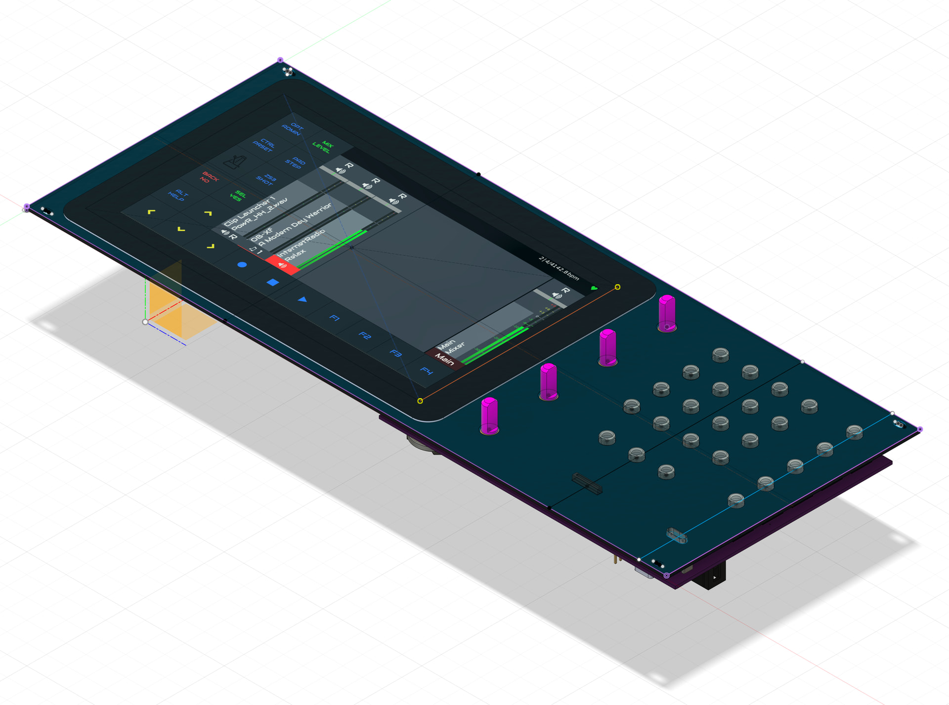
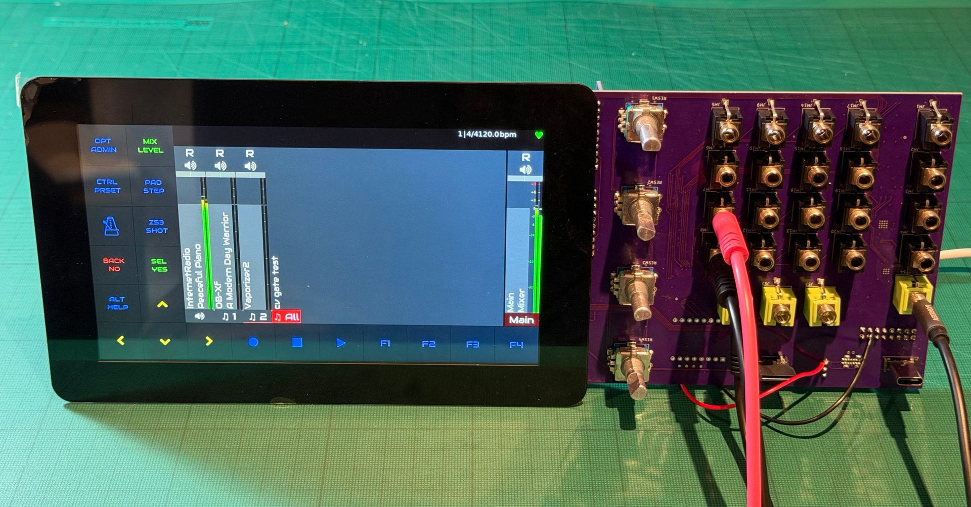
It uses a RPi Touch 7" display, RPi5 and a custom PCB with combined V5 architecture Encoder/MIDI/Audio, together with CV/Gates and Eurorack power rails. This will fit into a 64HP Eurorack. The CV/Gate section can be populated with the Zynface circuitry or Pico 2350/MAX11300 (once I write some code!)

I am testing the first board with Zynface circuitry populated.

Encoders, MIDI and Audio all work and it sounds great :slight_smile:

However, when I enable the Zynface circuit, using the Zynaptik configuration the encoder switches stop working and Zynface is not configured correctly (outputs are floating).

I also get the following error in the UI log on startup:

ZynCore: write_pin_zynmcp23017(0) => invalid pin!

If I then adjust the Wiring configuration to Custom 16Xio and 4Xda the Encoder switches return and the 8 gates and 4 CV outputs behave as expected, so the hardware is working.

It looks like on boot the MCP23017 for the Encoders (0x21) is being corrupted by the MCP23017 for the Gates (0x22). Both switches and gates are on the respective GPA ports as per V5 and Zynface schematics. I notice that the original Zynaptik address was 0x21, which would conflict with the Encoder address.

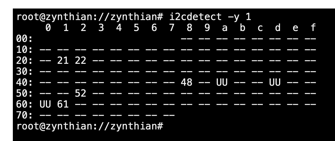
The I2C devices are read as follows:

0x21 Encoders (MCP23017)

0x22 Gates (MCP23017)

0x48 Control ADC (ADS1115)

0x4A Audio ADC (PCM1863)

0x4D Audio DAC (PCM5242)

0x52 RTC

0x60 Headphone Amp (TPA6130)

0x61 Control DAC (MCP4728A1)

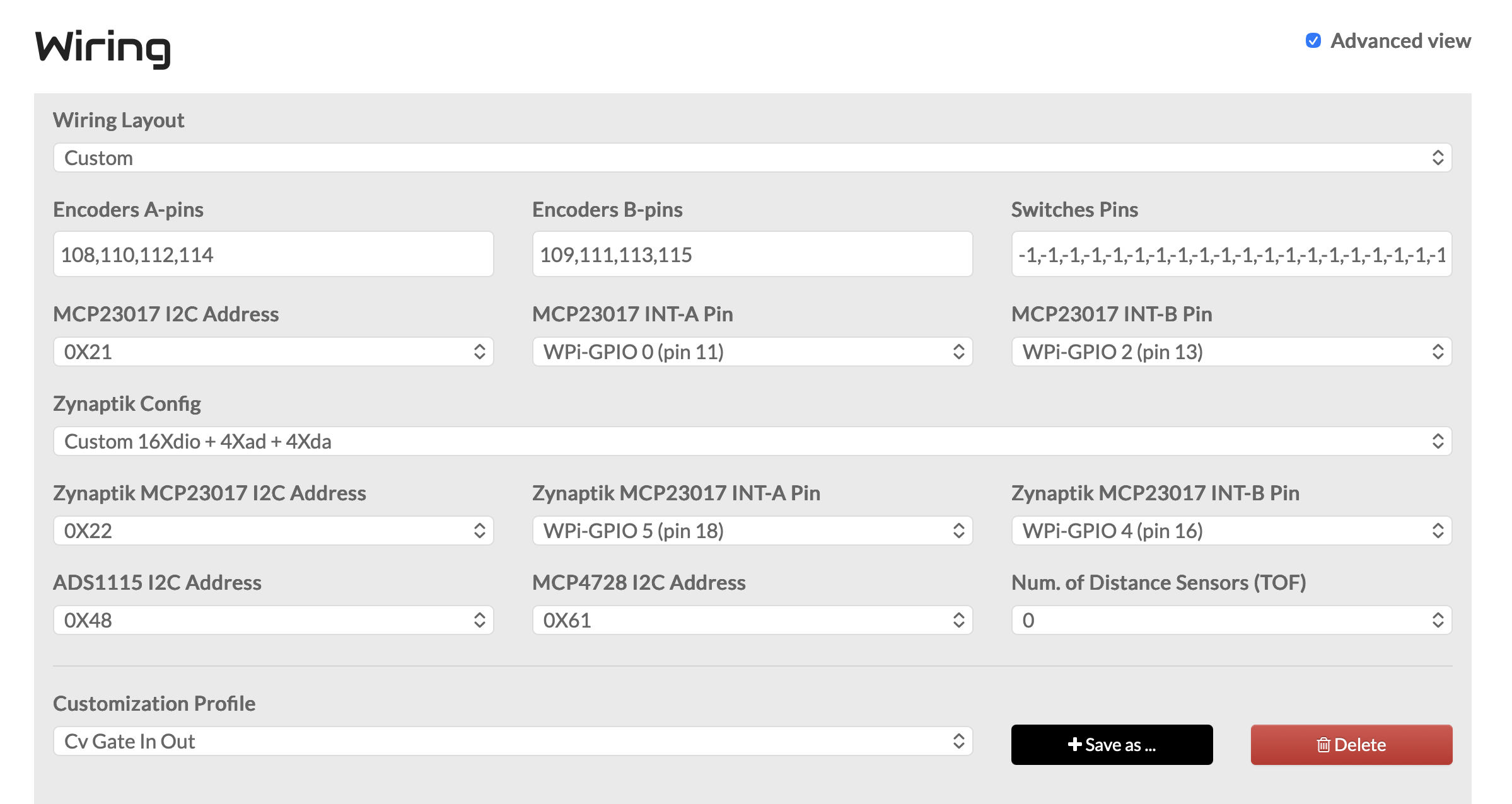
Wiring Config as follows:

Switches Pins:

-1,-1,-1,-1,-1,-1,-1,-1,-1,-1,-1,-1,-1,-1,-1,-1,-1,-1,-1,-1,-1,-1,-1,-1,104,105,106,107

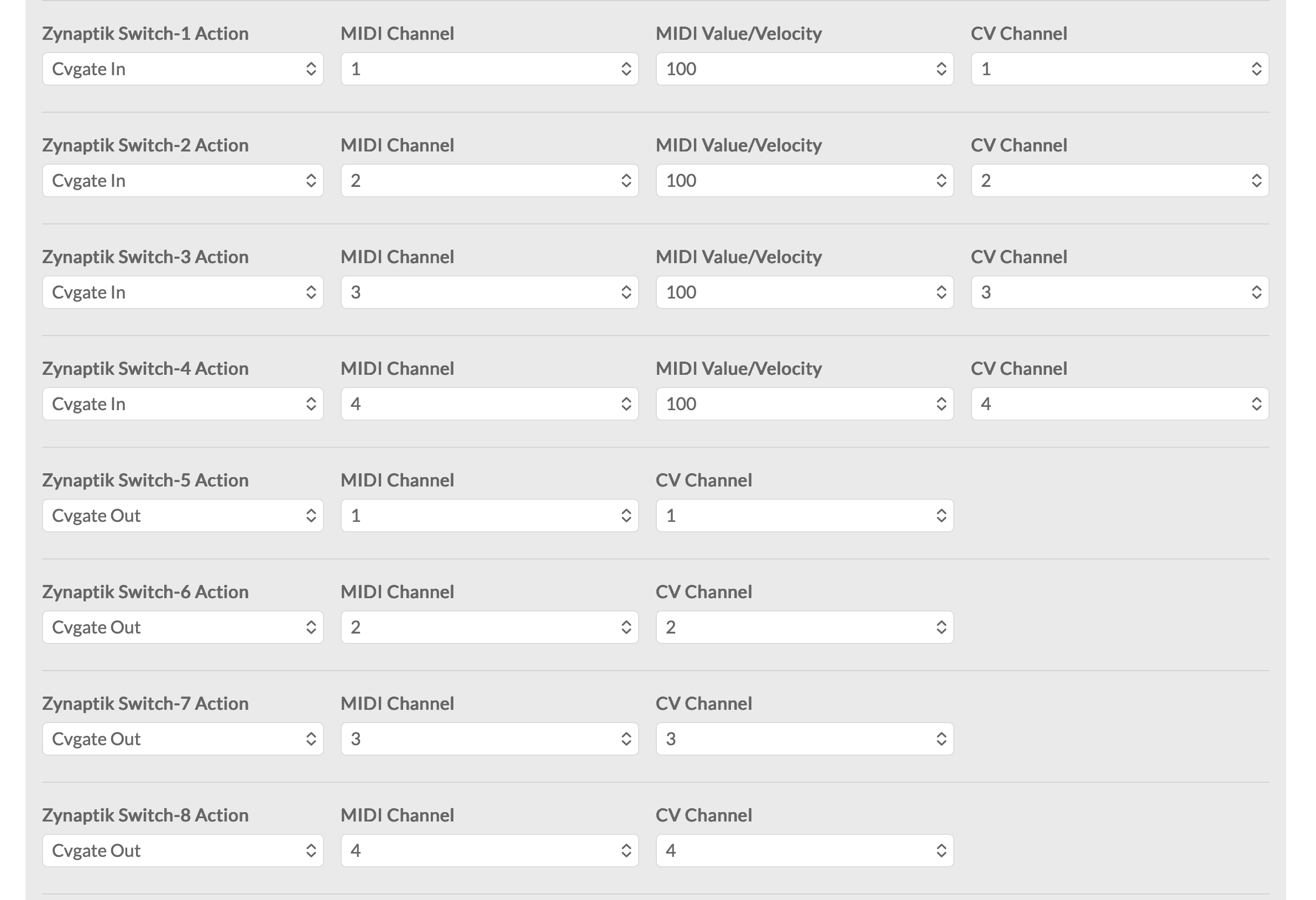
Zynaptik Test Config:

@jofemodo I believe you are the CV/Gate architect, does this all make sense?

I would like to understand how to create a Wiring layout for this board which will boot consistently and make sure the MCPs have the correct addresses and interrupts assigned. Can you help?

Then I can move onto the Pico/MAX11300 implementation.

Thanks in advance.

3 Likes