Continuing the discussion from [New zynthianOS release: Stable-2306]
A Place where the LED side of the zynthian world can bear fruit…
Meanwhile, an early prototype at a recent zynmoot meeting . . . . .
Continuing the discussion from [New zynthianOS release: Stable-2306]
A Place where the LED side of the zynthian world can bear fruit…
Meanwhile, an early prototype at a recent zynmoot meeting . . . . .
The relevant base code is here:
And here is the specific details for the 2 zynthian devices that currently integrate feedback LEDs:
As you can see it simply uses the “rpi_ws281x” library, that allow full controlling of ws2812 LEDs and similars. As you probably know, these LEDs are RGB devices that can be controlled with a single data line (serial protocol). You can connect a large number of these LEDs in serie, passing the data line from one to the next. For controlling the serie, you need a decent timing, that you can achieve in the RBPi using several techniques. We firstly tried with the PWM pins, and it worked, but we discovered later than using SPI subsystem is more efficient, so this is how we do it now in V5 and Z2.
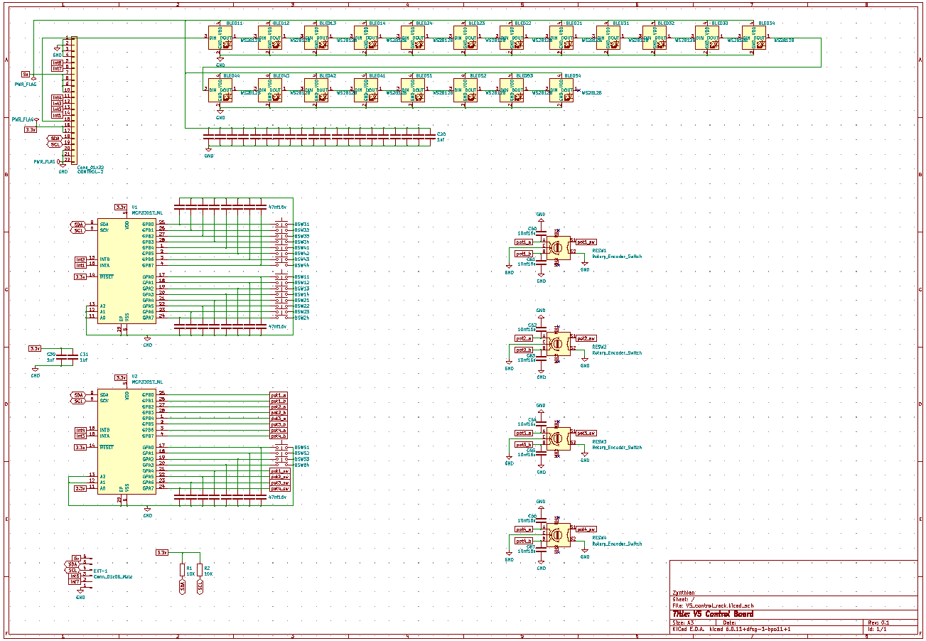
For the more curious souls, this is the V5’s control board schematic:
Enjoy!!
...
self.dma = 10
self.pin = 10
self.chan = 0
self.num_leds = 20
So V5 uses GPI 10 which I believe is the BCM GPI numbering scheme so appears on header pin 19.
I understand that PWM conflicts with the RPi onboard sound which uses this device so should be avoided. Did you have such issues with your Z2 V1 @jofemodo?
There are a lot of capacitors in the schematic. Are they near each LED chip?
I read:
I wonder if this is considered with the overclocking and power saving modes in Zynthian?
Yes. This was the primary reason to look for alternatives to using PWM pins.but in fact, SPI is more efficient and it takes less CPU cycles.
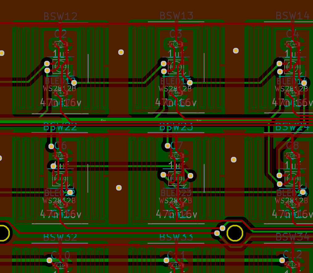
Exactly. One decoupling capacitor close to each LED. A second debouncing capacitor close to each conductive switch footprint.
On Z2 we used a 2 layers design, having the capacitors in the bottom layer, just down the LED, that is in the upper layer, on the foot print for the conductive silicon button pills.
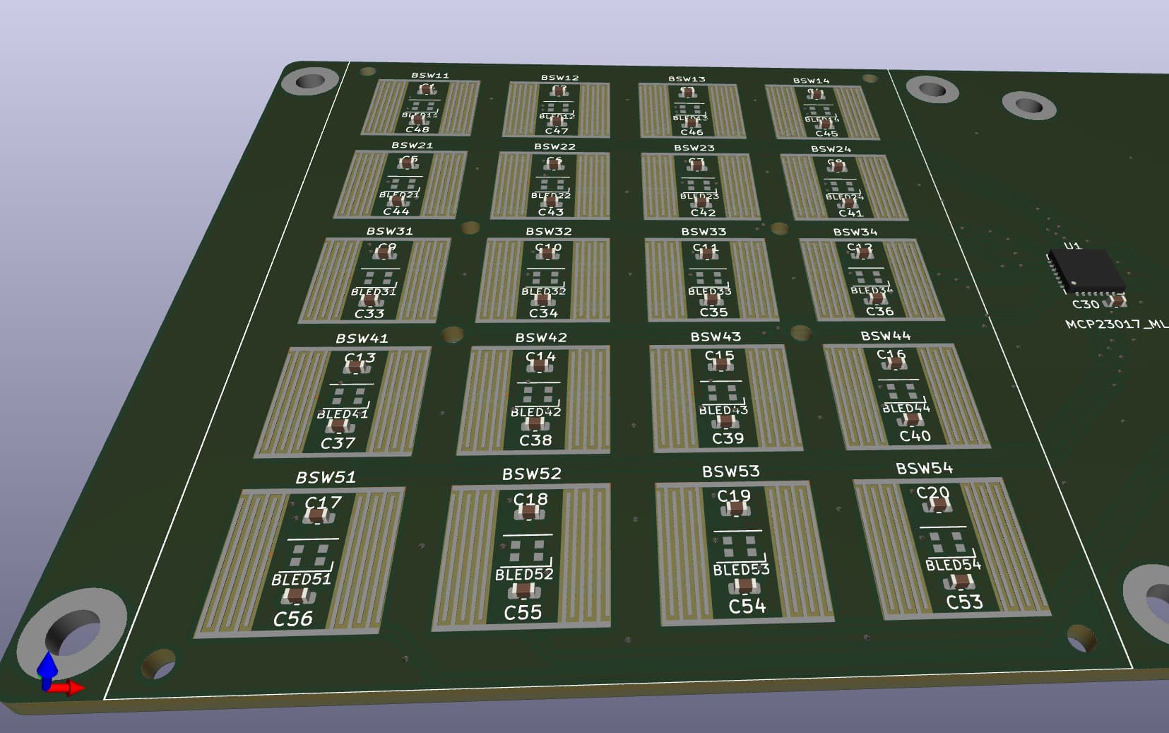
On V5 we decided to simplify things and we managed to lay 1 x LED + 2 x capacitors in the same layer, inside each silicon button footprint. Cheaper & better.
Would a 1 pixel unit offer zynthian status colours…?
My 2 cnts… When you want to off-load the handling of the LEDs, why not use a small MCU like the RP2040 (which is even more cheap than the 23017)…?
Additional MCU and related firmware add extra complexity. This would be OK if we really need it, but currently, LED management is not a problem for the RBPi4 and it consumes very little CPU when using the SPI pins. So, we prefer to keep things simple, avoiding extra MCUs with custom firmware to maintain, update, etc.
Regards,
Just wondering, since adding a additional 23017 to the SPI-bus and the WS28XX are very timing sensitive, what happens when the first 23017 triggers lots of interupts and occupies the SPI-bus a little to long… ?
The 23017 is controlled by I2c. The SPI bus is exclusively used to control leds.
Regards!
Offcourse, I saw the 23017 on the render. So you use a 23S17…?
No. MCP2307 (i2C version!) is used for reading push buttons and encoders. LEDs are controlled directly from the RBPi’s SPI pins.