Zynthian dac adac light ready for codec development

Oh, so many questions and myths and assumptions in one, so please let me try to answer them in a quick and simple way. I am neither an engineer nor a shareholder of Skyworks, in case some assumptions come up.

The air gap is really a silicon barrier. You’ll feel that instantly, once you bite on it. [clown mode off]
The radio transmission is in the nano-power area, so do not compare that to an IF of a radio. There are no emissions. The resulting noise on the signal lines, also visible in the eye-diagram and shown on the DS, are so far off-band, by at least four octaves on the digital domain and even orders more on the analog domain, they can easily be quenched or quench themseves in the next stage. The benefit is already, the ultra wide spectrum noise of the Pi can not pass the Si8662BC and so only the working frequency spectrum of that chip has to be quenched, making things actually easier on that part.
Now come the Audiophile and scream out “Jitter!”. That is another audiophile myth, as modern ADC and DAC already have some builtin PLL or similar (with their own jitter) and the frequencies involved are magnitudes of sample rate, statistically levelling off any jitter to an irrelevant level. The jitter issue was relevant in the era of parallel convertes, where jitter in the sampling clock had direct impact.

First of all, there is no ground in Zynthian, as there is likely no ground in the entire setup of many use cases, as most power supplies these days lack that ground connection and even if they have one, this is only connected to the primary side of the converter circuit and the secondary side is still connected via XY capacitors to mains, causing a whopping half mains voltage of common-mode injection plus the mains noise to the metal parts and the so-called ground plane, which in fact is a noise plate, considering the signals added by the switching converter and other parts of the setup.
The Si8662BC (or another one of that series fitting the purpose) alone does not decouple the noise plate from the DAC / ADC / audio stage. To achieve this, an isolated DC-DC converter is needed in the power supply, like this one: TES 1-0522 | Traco Power
that also doubles as a dual rail supply to provide a negative voltage as well. For the power output, additional filtering and LN/LDO are required to make a clean isolated power supply, that much should be clear. That way, an isolation barrier is inserted between the noise plate and the audio ground and between the power supply noise rail and the audio power supply.
If now the ADC part and the DAC part each together with their own amplifier and filter stages are decoupled each on their own, with own isolated power supply, own isolated digital path, then any kind of “gound loop” is broken as well.

I hope this text in it’s entirety gives the answer.

First of all, many audio electronics these days have no differential audio lines, some due to their nature (guitar amp), most due to cost or practicability (bulky XLR connectors).
A differential transmission only has the power to quench common-mode interference while it is not saturated. Now imagine the switching power supplies screaming through the world and the 5V supply of the OpAmps in today’s DAC or ADC gimmicks. The functional headroom of an amplifier can not be outside the supply rails. That is why professional audio still uses +/-15V supplies (or more) even today.
A transformer is expensive, really expensive if it is a good one, but still it distorts and colours the sound, a cheap transformer even more than a well-manufatured one. Due to the nature of how that works, there is always an unavoidable impact to the signal. A good DI-box can cost more than the isolated sound card and it still is bulky.

Even this aspect is enhanced by isolating the digital path and the power supply path. The spectrum on the digital side is lifted to mainly off-band, something a bus transciever could achieve as well, but without the benefit of breaking connection to noise plate and supply noise. The DC-DC converter wil output a dirty supply voltage, but with still a narrower spectrum noise than the Pi, again easier to filter and make silent.

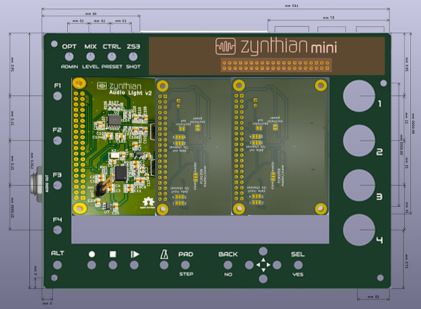
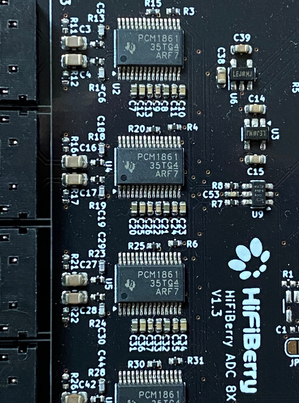
The original design of the 8x sound card system is only handling i2s and power signals, making things really easy. The sound card does not offer differential audio. Audio circuit has no headroom. It would be just another sound card.
Or it could be something really outstanding! Eightfold!

1 Like

Here is audio input test recording using aida-x (default amp) → Gxdigital_delay_st → Calf reverb (Disco verb preset) with no buffer in front of it. It still sounds good. I have removed amp hiss using Denoiser Classic VST plugin.

6 Likes

I don’t know how far you are with your next PCB design. It may be good if the PCBs could be mounted adjacent with the same spacing between jacks. The first iteration had more space between the edge of the board and the jacks than between the jacks. If you put 4 jacks (2 in and 2 out) across the board then it may not layout nicely in an enclosure because you would end up alternating between input / output for each channel. If we used stereo jacks for input and output (which I dislike, preferring two mono jacks) then you could mount the boards vertially so that inputs are at the top and outputs at the bottom.

I don’t have an ideal answer but please consider how we might mount PCBs to present multiple inputs and outputs in a logical way.

I don’t think that I can fit hardware required for 4 in/outs (double what we originally tested) on the standard rpi hat size. Even without jacks ( just standard JST connectors) it would not fit.

After adding two 3.3V LDOs and their caps, missing oscillator caps and additional solder jumpers for fully configurable card there is no much space left.

Did you maybe think to create a bigger - non standard hat?

I wasn’t really considering hat format. If you want to stick with that format than my comments don’t really fit. Looking at the board on my desk it occurs to me that it could be formatted to allow multiple boards mounted with a consistent spacing. Maybe your board doesn’t align with these aspirations.

Board should aspire to this. However, when stacking boards it would be better to use JST connectors and panel mounted jacks so that less height is used instead of jacks on the board.

Standard female 40pin header is not high enough for jacks. However it is high enough for horizontal JSTs.

Hi @stojos, @riban and other contributors!

Has the Zynthian DAC Light Kicad design been already published? Since I’d be interested in getting one audio card AND also a fascia for my Zynthian Mini V2, I was thinking about rearranging the PCB to get something like this mockup:

That way:

  1. Costwise this could make sense, since the real estate for the display is “already paid for”, even in a nice black finish. Bonus DAC/ADC boards could be precutted.

  2. The brown area could be optionally used for a first DAC/ADC circuit on the back, already configured as master (no additional headers to short), at the aesthetic cost of showing the back of a through hole “GPIO” header. But the whole header is not needed here, just the pins to connect to the full size header at the bottom of the mini PCB. And this could be covered by a nice zinthian logo sticker :-).

  3. The display area could accommodate one DAC/ADC board with full size audio connectors and another one with JST connectors, or even maybe three of the latter.

  4. I also want a USB-C data/power splitter (very simple design). There could be space for it at the back to the right of the encoders.

Thoughts?

I have not published design of adc dac card on GitHub. I can do that on my GitHub as I did for miniature design but I would first do this after I tested it. I still haven’t ordered latest design. With mini v2 and first adc/dac prototype card and with latest addition of v5 to my arsenal I am mostly playing during my free time. :wink:

In regards of adding it to mini v2 I would first enhance existing thru-hole pcb design with a connector for a cheap adc card as we did for dac card and add thru-hole oscillator required for such setup. This would still be full DIY project where people would be able to order PCBs and source components themself. Here is for example additional pcm1808 adc card that can be purchased cheaply and added to mini v2 design PCM1808 105dB SNR Audio Stereo ADC Single-Ended Analog-Input Decoder 24bit Amplifier Board Player Module

I am also planning to design enhanced zynthian miniature version that will use smd components and replace current pcm5102 card with onboard adc dac smd components.

Finally, I am planning mini v3 with all current thru hole components (apart for switches and rotary encoders) converted to smd and adding two stereo dac adacs but also keeping a HAT connector for additional dac adc cards. I am thinking to still keep switches as thru-hole so that user can solder them or not and use onscreen buttons instead. This would reduce pcb production cost because all smd components would be on one side.

Before producing and selling enhanced miniature, mini v3 and standalone adc/dac card I am looking at possible sale distribution options. @jofemodo and I already talked about possibility to host such prebuilt PCBs on zynthian shop but there will be a need for shop enhancements for hosting products not produced from a core team and some work on shipping logistics.

1 Like

Hi stojos
this all sounds super interesting, do you have a timeframe for the mini v3?
In the meantime could you shed some more light on how one would connect the pcm1808 to the current mini v2? Would I use the current soundcard for the output and this new one for the input?

You need to add shared crystal oscillator to drive pcm1808 chip that also need to be shared with pcm5208 as well as with rpi. To connect all together you will need a dedicated pcb that will host pcm1808 board and a crystal and connect that pcb to rpi using mini v2 hat and to set pcm5208 board to use the same clock and speed. Possible but not easy.

Understood, so nothing that a rookie electrician like me can handle :slight_smile: I will wait for you to release the pcb or give this codec zero a try.

I wonder whether HiFiBerry releasing their DAC8x and ADC8x add-on might mean there are overlays and kernel modules (device drivers) available upstream that we could use for this project, rather than depending on my kernel module that I have not yet submitted upstream. Someone should try…

ADC dts is the 6.12.y branch:

they use rpi-simple-soundcard.c and here

So it looks like the driver can check if the ADCx8 is present or not in addition to the DACx8.

it’s a recent addition :

I wonder what kind of ADC chip it is