I suggest we fit in a ‘beer, rock and loud engines’ chapter!
More seriously (if being more serious that booze and noise is among the realm of possibilities on Zynthian Planet), I really dig your diy magnetic keyboard @wyleu, it really appeals to my sens of creativity!
Can you play it like a tuned theramin ?
Is it ‘almost touch sensitive’?
Cool stuff… one might even consider a tiny 
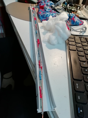
The Marvellous Magical Magnetic Musical Meter Stick.
Heave! Heave!
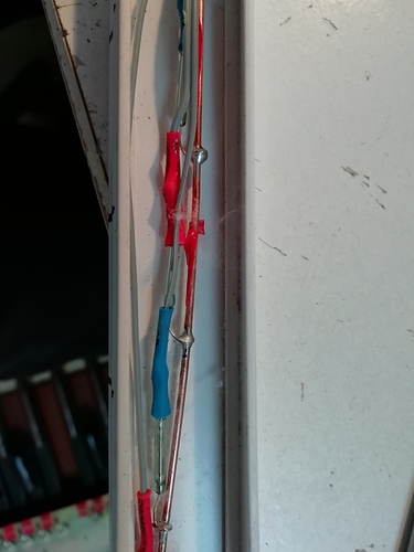
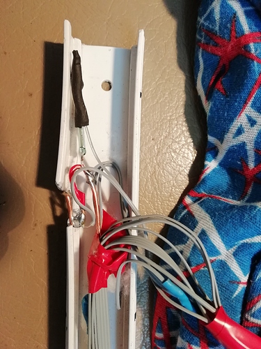
More internal detail of what I suspect is very much the first go at the magnet reed switch alignment.
Magnet alignment seems important and horizontal positioning can operate two switches at the moment. I’m filling the trunking with cotton wool and forcing the reeds down into the bottom corner of the trunk…
I suspect I will make it so the magnet is normally adjacent to the switch and the pedal descending will pull the magnet away from the switch line but that does rely on magnets and switches lining up carefully. I am thinking more about my original idea of an clear acrylic tube to mount them.
I hate to admit this but I don’t understand. This reminds me of nothing mankind has ever produced, a hybrid between electronics and plumbing. Maybe it’s because I just got out of bed, or maybe you really are a step ahead of humanity.
Do, simple question ; how does it work, technically?
It has something to do with magnetic induction obviously, but if it were just ‘1/0’ switches you wouldn’t have soldered that copper lead would you?
And how about the reception of the incoming -analog?- signal ?
Did you draw some electronic schedules or something, those I can understand and read.
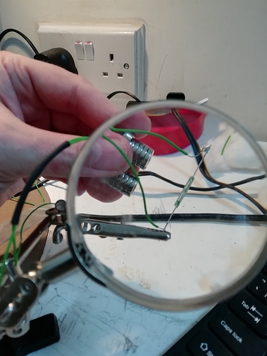
A reed switch is an electronic switch which is actuated be a magnet. Wiring it to the Zynthian as extra switch (or via some other interface) allows triggering functions by proximity of a magnet to the switch.
Means… the closer you are to the North Pole, the higher note-on velocity…
Ok… sorry… I won’t do it again…
(<< liar)
(Note that it also works with the South Pole)…
This I know, I was wondering if there would be any form of ‘approach sensitivity’ or, as mentioned @opus.quatre, an influence on the pitch or the level, in fonction of the distance
I’m not sure that velocity is easy to use on a pedalboard… maybe it is, but I would not rely on my feet that much…
Oh but it would be lots of fun ! I must admit that at first I didn’t understand why anyone would use this type of technology just for switching ‘on/off’, hence my suspicion of this hiding some special features like ‘distance detection’ (like a sort of theramin like switchboard, allowing smooth overlapping and ambiance changes).
It was just my imagination, sorry guys.
Optocouplers might be a fun option aswell!
I guess that the reason why people use this kind of technologique isbthat it allow having completely indépendant circuits, electrically speaking…
I know that those magnetic switches are used a lot by organ builders, and I believe, mainly for electrifying classical enormous pipe organs with a lot of “registres”, pipe sets…
I totally ignored that
THe original pedal board had silver wires which became rather unreliable, that why I’m looking ar reed relays but I’m now wondering about microswitches.
I’m not designing with velocity in mind. I don’t think it’s a great bonus in pedals . . .
the Studiologic MP117 is velocity sensitive, but I can’t find out if the Taurus wasn’t or was. I’m suspecting it wasn’t.
https://www.amazon.co.uk/dp/B00C4VTBF8/ref=as_li_ss_tl?language=en_US&ie=UTF8&linkCode=gs2&linkId=bc87829734e5a0e7c543821125ac29f2&tag=heavycom-21
This is one of those instruments that I’m going to have to learn to play once I’ve built it.
The magnet sensitivity & debounce are the primary concern at the moment.
The switches are connected between a Ground rail and the last 13 GPI pins on the Pi
PEDAL_RPI_MAPPING = [
Note Name MIDI note GPIO pin.
['C3' , 36, 40],
['C#3', 37, 38],
['D3' , 38, 37],
['D#3', 39, 36],
['E3' , 40, 33],   # Wiring Error F <> E
['F3' , 41, 35],   # Wiring Error E <> F
['F#3', 42, 32],
['G3' , 43, 31],
['G#3', 44, 29],
['A3' , 45, 26],
['A#3', 46, 24],
['B3' , 47, 23],
['C4' , 48, 22],
]
Given it’s written in python I’m using callbacks to operate things .
def add_callbacks(self):
    for reed in self.reeds:
        GPIO.add_event_detect(reed.io, GPIO.BOTH, bouncetime=200)
        GPIO.add_event_callback(reed.io, reed.my_callback_two)
def my_callback_two(self, channel):
    pressed = not GPIO.input(channel)  # pressed == 1 for magnet close
    if pressed and not self.pressed:
        print('Pressed:', channel, self.name)   #NO enabled
    elif pressed and self.pressed:
        print('STILL PRESSED', channel, self.name)
    elif not pressed and self.pressed:
        print('Release:', channel, self.name)  #NO Pulled up
    elif not pressed and not self.pressed:
        print('Note finished .  . . . ')

    self.pressed = pressed
    print('--------------')
Obviously the print statements need to come out for decent testing, and I’m not sure if the grab of the pin value at the start of the callback isn’t getting confused by contact bounce.
I will probably try with a 100 n capacitor strapped across the relay to see if that makes things a little less sensitive.
Also, the shape of the magnetic field that operates things needs optimising, a thin magnet with N & S on the flat faces seems most effective and I need a magnet that will reduce its operating abilities within the 13 or so mm that pedal moves down.
The final arrangement is probably to have the 13 magnets all energising the switches so they are closed and the pedal going down will move the magnet away and thus allow the contact to open, but I’m having trouble aligning things for this case and the tests are a little dispiriting at the moment. I suspect the mark two will be VERY precisely aligned with the magnets, but that’s why you build prototypes.
I think I’ve proved that you don’t’ need anything other than a PI to make this work, The callbacks don’t chew anything like the CPU that polling the pins did, but I suspect a C implementation would be far better, and then there is the issue of does one make this a JACK MIDI device or integrate it into the zynthian world as an i/O option instead of encoders.
I not back at work till Tuesday so I can put long bouts of thought into it with furtive acts of programming to support it. I must be on the right lines cos my Laptop overheats when I try to run PyCharm to do the zynthian development so presumably the Gods of Python & Pi are looking down on all this with evil intent !!!
See the catalogues of Kimber Allen…
https://www.kimberallen.co.uk/our-catalogue
Or
If you want variable control using magnets then there are Hall effect devices. Some reasons for using magnets and reed switches is to provide electrical isolation and reduce wear / oxidation.
We also use optocouplers for detecting the height of vehicles in what we call ‘optic gates’. (French tollways)
The priciple is very simple and might be easily be transposed on a note-detecting system (picture a guy waving his arms up and down, triggering a bunch of oscillators  !)
!)
Or one might consider using variation of impedance as used in radio detecting systems like the ones we use for counting trafic on highways. The impedance and thus the resistance varies in fonction of the volume of metal hovering over the woven loops, detecting speed, weight and size of the vehicles. we also use what we call SmartSensors which actually work the same way but using microwaves to detect shapes, distance, speed (pitch, velocity, aftertouch…)
Reminds me of the very simple Arduino Radar one of my sons build, detecting objects aswell as it’s distance. all of these varieties and more could be transduces into musical information, using midi maybe?
Oh what a wonderful world !
@wyleu and @Vincent : you might want to see this page…
https://www.midi-hardware.com/index.php?section=prod_info&product=HALKA
I’ve used hall effect sensors in a home made flow sensor for solar heating, and they work well, but This is an attempt to do things without external active electronics. I think I’ve proved the Pi side of it but the mechanical alignment is proving tricky.
That’s the reason why I sent the previous page, mayube you will find some tricks or treats and tips and tops of the pops…
The section about orientation of magnets certainly is true, I notice considerable different results depending on how things are orientated, and I didn’t ensure the first batch of switches all aligned the same way. Of course they are meant to sit inside a coil which will align the magnetic field along the switch axis, so maybe version two might embody that concept. And also make the ribbon cable long enough to allow all orientations of the touchscreen… . . .
The above rig conducts at some distance but I’ve placed one of those magnets next to the reed & in certain orientations you can get it to not sound at all so Orientation must be consistent !!
Lot’s to learn. IF/when it works I will be very pleased, but I have noticed the mono/stereo options now avialble to zynthian-alm.local (Pi3 in a small aluminium box with an audio injector ) so I might well investigate that for the evening. . . .
You get Sooooo much time when you dispense with a social life !!!


