Zynthians never die…
Wish that life were so simple, let me lead you down into the dark dripping cloisters where rag encrusted peasantry toil endlessly on testing the vagueries of the zynthian’s performance.
You’ll have to put on these headphones, as the first seven vaults are devoted to @MrBroccoli & his team of formation screen smashers . . . 
we tend to let them get on with it. . .
I’m just very good at stress testing.
1 Like
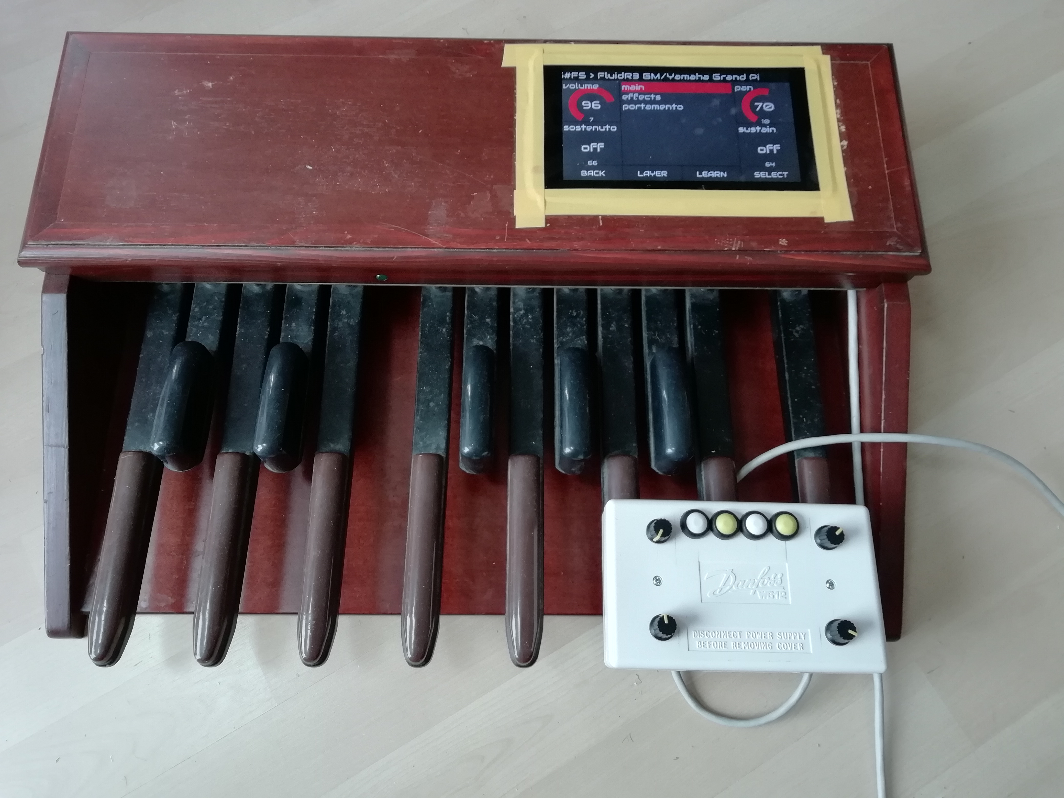
So pedal board fans, progress has been made. . .
We now have a socket mounting panel fashioned from the plastic top of Pi boxes
and Encoders in a separate box over two metres from the zynthian!!! and they work! No 12C line drivers required . But I might still add them.
So I’ve now got controls at hand and guitar level and display down on the ground.
4 Likes
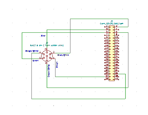
Now it’s over two meters and two GX12 6 pin connectors in circuit…
Still works.
For reference GX12 connectors are a pain to solder, especially with multi strand CAT5 cable.
But I’ve got there…
And now a clever re-alignment to match the four switch appearance of the new world order… The announcement was literally six hours after I’d built it that way !
So now I have a v4 without trying 
You may start to see some reliability issues at that length. The cable capacitance will start to impact slew rate significantly at 1m when running at 100kHz. Dropping to 10kHz would allow about 10m cable before becoming an issue but the MCP23017 does not seem to support that rate. (I don’t know if the RPi does but if it does then you might be able to use the I2C interface I developed for Arduino / STM microcontrollers (some microprocessors support 10kHz). Of course empirical testing often trumps theory but you will want to test in extreme environments to ensure you are not just lucky it is working on the edge in your home then it goes bonkers on stage. I am likely to be touching the I2C code soon so let me know if you want something specific.
I’m looking at the I2C accelerator chip as a possible extra level of reliability…
Of course a signal conditioner can improve the signal and is useful for extending a circuit, e.g. device-a->conditioner->device-b but if your signal is already deteriorated beyond repair it won’t help. There has to be sufficient signal to recover, i.e. SNR has to be good enough in which case the I2C device can probably manage by itself. Again, more theory but I have done this stuff so a bit of experience too  . If you want to extend the cable length with active circuitry you may be better off with a balanced line driver / receiver like RS485. (There was another long distance protocol we used in the 1990’s but I can’t remember it’s name - it had ‘100’ in the name.) I ran reliable data exchange on these protocols over hundreds of meters on standard twisted pair cable. Given your use case of just signalling on / off and maybe some slow changing data, a slower data rate seems like a good path to explore but you are currently not experiencing issues so maybe all is fine.
Another way to go is to use the network interface on the RPi. If I understand your use case you are joining two RPi together so they could communicate over IP or another network protocol. (The kids might not know there are others!)
I think, from investigating, the pi runs its i2c at 50kHz.
Yes I was surprised how well behaved its been as has been said it’s really a protocol for within an enclosure and the fact it seems OK on 2metres of twisted with no shield. The actual use case only needs about a metre of cable so this was a test piece.
The pedal board will be getting a zyntatik a/d board to allow swell pedals and some interesting experiments with those hall effect analog signals so i2c as a standard within a zynth has had a fair bit of contemplentary thought. (you know the sort of thing…  )
)
As always I vacilate between i2c and USB. USB is connector simple. There is a 7pin GX12 connector so I could get one more interrupt but I wouldn’t like to solder too many of those! The trouble, for me, with usb is the amount of arduino you need to do downstream but that just an area I know next to nothing about, and the hassle of providing mounting and such like. The drive for the USB qwerty keyboard stuff was developed from the ease of adding USB devices… No soldering, no hole drilling, no worrying about physical interference inside small, sometimes tiny enclosures.
As a simple all in one extender it seems rather nice, but as you say the real test is in an unpleasantly noisy electrical environment. If it turns out to be a problem then buffers are probably the way to go, bu I don’t know how well behaved the interrupt lines might be.
Might have spoken a little too soon on Encoders over 2m on i2C.
I’m seeing what I recognise as a standard encoder failure mode,
A parameter in a layer will advance from lowest to a higher value, but fall back to zero when it gets the slightest touch of a back turn.
I’ve seen this with intermittent edge connectors, on one encoder with 1/O mapped encoders but in zynthian4-steel.local it happens on all encoders. Always seems worst on Select, but that could be where I had it occur on zynthian-amp.local, which had a multimeter provably dodgy connection on one of the pi/amp 40 pins.
I will try it on the pedal board just to check and then cut the cable 1/3 2/3, stick two new connectors on the ends and see how those cables behave.
The I2C interface used for standard Zynthian encoders just turns the pulses into I2C messages so any interference could lose the plot. The I2C interface I use does all the decoding of pulses and filtering then presents the encoder state over I2C which may be less susceptible to interference. For simple switches there is likely to be little difference but for encoders you are really asking a lot from the protocol. You ma need to dig out your Idiot’s Guide To Interfacing soon and get stuck into microprocessor programming. (It is unlikely to be Python  .)
.)
Seems to be ok on Pedal, but there isn’t any extra i2c load on that.
Time to cut down the cable 
The new,new,new,new way forward.
which replaces…
2 Likes
Well the 12c on the zynthian4-steel.local doesn’t respond properly on 'any length of cable.
It increases correctly but back turns reset the value to zero.
So there are some limits to what one can do with 12C in these scenarios.
Basically if you have two devices on an i2c bus you really have no opportunity to separate them by any appreciable distance if you want to use the parameter encoders.
The menu selection stuff works so for a setup option you have control just dont let it near the parameters
Buffers would be the next try, but frankly, I wont be adding any extra loading on the i2c bus from pedal and that seems to work (till it gets to somewhere performance critical no doubt)
Make sure when you try to connect to the MKRZERO that you don’t have two USB cable that are BOTH Power only … Growl…
1 Like
ok first arduino error message. . .

The prize will be a weekend in Southend…
The second prize will be two weekends in Southend…
You need to install the required libraries.
Yes, that bit I got but which ARE the required libraries ?
for a start none of them have .py on the end . . . .
Just a fast guess:
- Go to
Tools / Manage Libraries - Search for
Pluggable - I am getting two results, one of them is
USBMIDI - Install
USBMIDIand hope that it also installes something likePluggableMIDI
Regards, Holger
[EDIT]
Maybe read here?
Sadly already installed USB midi.