Adding encoders to a home built zynthian

Hi everyone,

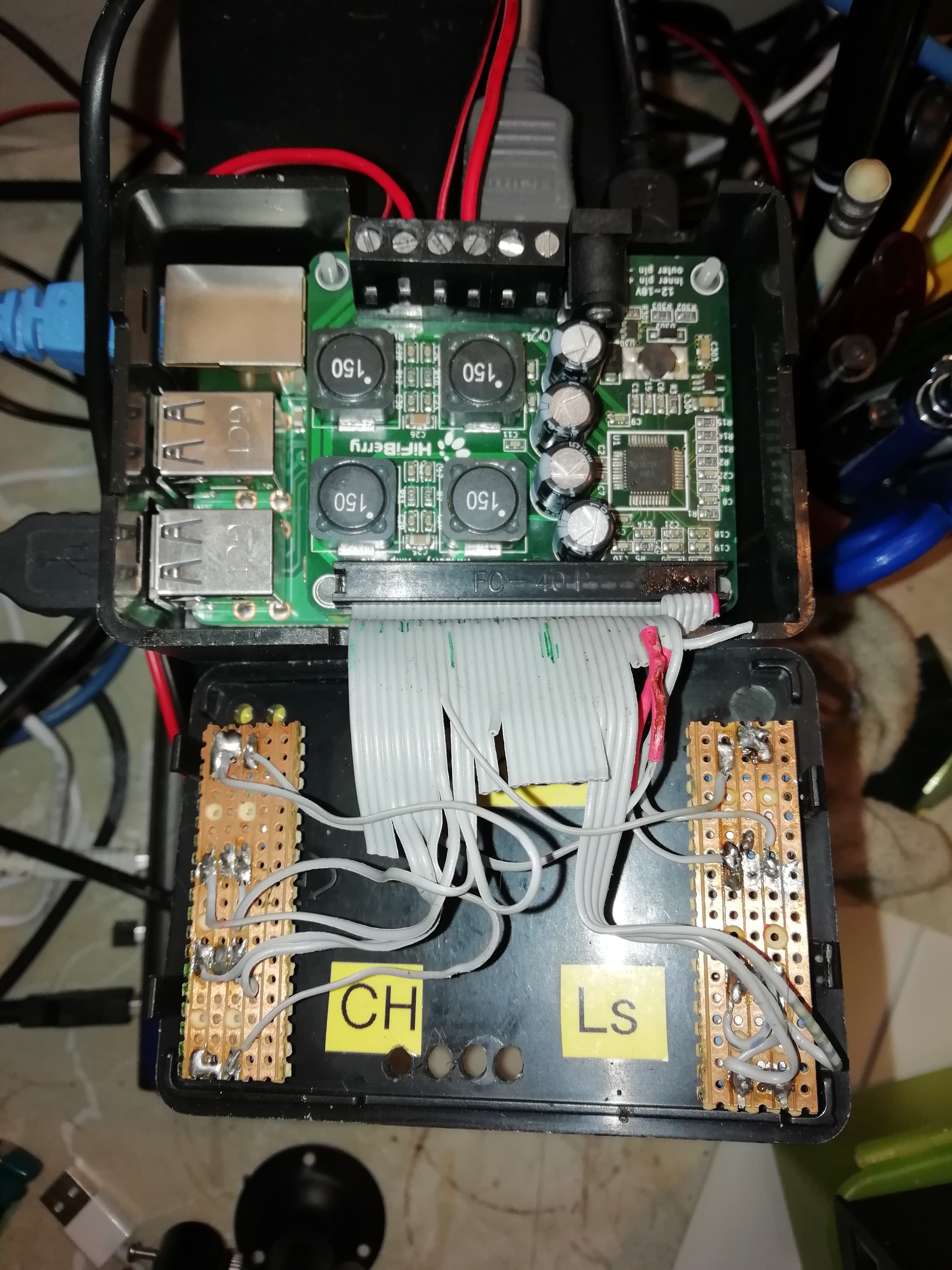
first I want to say hello to this lovely community, since I am totally new to the board and to RPi stuff in general. I managed to assemble a basic Zynthian using a RPi5 with a 8" Waveshare HDMI Touch connected to my Focusrite Scarlett 2i4 and was already able to play some music, pushing some gigabyte-ish Steinway D samples to the machine and already used it in my bands rehearsal.

Next I wanted to put everything in a nice wooden cigar box and am now in the process of ordering stuff for it. Plans are for now:
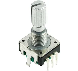
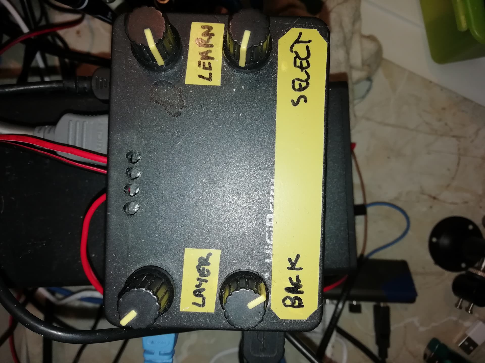
  • 4 Encoders to GPIO
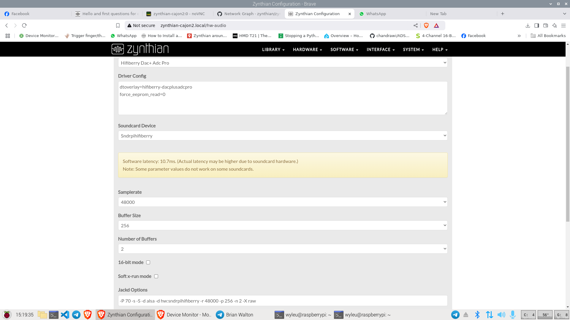
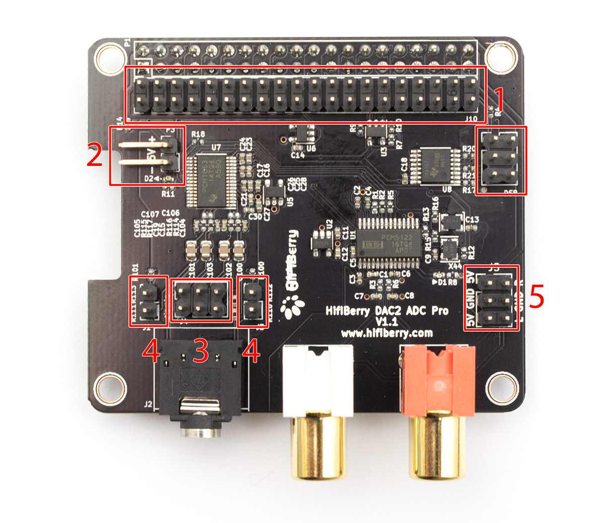
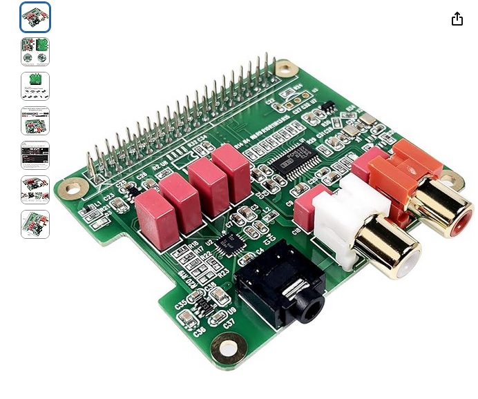
  • replace Focusrite with Hifiberry DAC+/2 ADC and add stereo I/O Jacks

Like already mentioned, I am completely new to the topic and could need some help. You can imagine I have tons of questions already, but to not flood this forum I’ll start with the encoder subject. I promise, I already read through all threads you can find by search terms “encoder”, “GPIO”, “MCP23017” and so on.

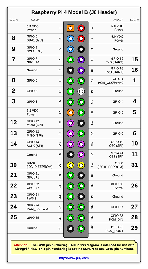
I created this table for my own conciderations:

Notes BCM WPI Name Pin Pin Name WPI BCM Notes
Evtl. + All Enc 3.3v 1 2 5v
X HifiB 2 8 SDA.1 3 4 5v
X HifiB 3 9 SCL.1 5 6 GND 0v free GND
4 7 GPIO.7 7 8 TxD 15 14 X ZynMid
free GND GND 0v 9 10 RxD 16 15 X ZynMid
* 17 0 GPIO.0 11 12 GPIO.1 1 18 X HifiB
* 27 2 GPIO.2 13 14 GND 0v free GND
* 22 3 GPIO.3 15 16 GPIO.4 4 23 *
3.3v 17 18 GPIO.5 5 24 *
10 12 MOSI 19 20 GND 0v free GND
9 13 MISO 21 22 GPIO.6 6 25 *
11 14 SCLK 23 24 CE0 10 8
free GND GND 0v 25 26 CE1 11 7
0 30 SDA.0 27 28 SCL.0 31 1
* 5 21 GPIO.21 29 30 GND 0v free GND
* 6 22 GPIO.22 31 32 GPIO.26 26 12 *
* 13 23 GPIO.23 33 34 GND 0v free GND
X HifiB 19 24 GPIO.24 35 36 GPIO.27 27 16 *
* 26 25 GPIO.25 37 38 GPIO.28 28 20 X HifiB
free GND GND 0v 39 40 GPIO.29 29 21 X HifiB

While reading the corresponding thread about wiring encoders to RPi4 I cam across some wiring suggestions frim @wyleu . I noticed that both of them seem to use pins another post of the same thread recommends to avoid. As far as I understand from corresponding sources I should avoid Pins 3, 5, 8, 10, 12, 35, 38, 40 because of Zynthians Midi I/O and used Pins of the HifiBerry DACs. So I assume I could use the GPIOs marked with a “*” in any order. Do I get that right?

The other question is about the oftentimes mentioned capacitors. I understood from this forum that they might be needed, or not. From what I understood, I might consider to buy 4 100nF caps and 8 10nF caps and place them between the A(CLK), B(DT) and Switch(SW) pins of the encoder and the corresponding GPIO. My question would be if I can use any type of caps, like these. What I also learned by reading these threads is that I might or might not unsolder a resistor on the encoders pcb.

Ok, I’ll stop myself here. Thanks in advance for your kind help already.

1 Like

Hi @hannesmenzel! A warm welcome.

I would avoid using pins: 12, 13, 15, 16, 18, 22, 35, 37, 38 & 40 which are the I2S (audio interface) pins on RPi5. You may not be using all of the I2S ports if you use the HifiBerry 2 in, 2 out device but if you want more audio inputs/outputs you might want to use these pins. Of course, if you are sure you only want 2x2 and cannot find sufficient other GPIO then you will need to use these. (There are only 12 spare GPIO that will all be required for 4 encoders plus switches.)

No, they need to go between the encoder/switch pins and ground.

ZynScreen_v1.5 schematics and V5 control schematics contain everything you need to wire the encoders using an i2c-I/O chip named MCP23017. These are available on complete breakouts and provide an elegant way to connect buttons and things to Pi and you don’t get into problems with GPIO usage. Run the chip at 3.3V (!) as Pi’s GPIO are only 3.3V tolerant.
Capacitors at ecoders and button switches are never in-series, but bypassing to ground, as sort of denoising (some call it debouncing, which it is not).
47nF on each pin to ground are quite enough. Larger capacities will provoke flatter slew, making even more transition noise on non-schmitt-triggered inputs, then causing flase triggers.

Thank you for your fast answer. I considered the direct gpio layout since for now the 4 clickable encoders will be enough for a while. But I guess sooner or later I’ll consider the MCP anyway for some button action.

For the capacitors capacity: It was suggested here to use different capacity for encoders and switches. So what would you recommend?

Oh no, the table I used might be on the basis of the wrong RPi. I have to slow down a bit. I referred to the mentioned thread and the HifiBerry GPIO documentation, I could have noticed the wrong numbers.

How would a newbee get that done? Is a bread board a legit alternative. Should I solder a 100nF capacitor from the SW to the GND pin?

You should use 10nF capacitors between each pin of each encoder and ground. That is 2 capacitors per encoder.

You should use 47nF capacitors between each switch and ground. That is 1 capacitor per switch.

How you practically do this depends on what components you purchase and how you intend to mount them. You ideally want the capacitors close to the switch/encoder. If you buy raw encoders like this:
image
then you could mount these on some veroboard and put the capacitors between each pair of pins. I think this would be the simplest way to DIY this.

Thanks for now! Like expected there are some considerations open. I’ll happily come back when I made some decisions.

Well done…!!

Course if we heard what you produced. . .

Sorry, I still did not succeed with understanding what is needed to even order the parts for my plan. So if you would be so kind to help me with my considerations:

  • I still struggle with understanding how to get a custom encoder wiring together with any Hifiberry audio hat, no matter if wired directly to gpio or mcp23017. For the dac+ adc: are the 40 holes below the gpio connection duplicates where I could just connect things with a 40 pin header? for the dac2 adc the additional pins seem to be reserved for the dsp header. Are these gpio duplicates as well anyway? And how do I supply power to mcp23017 when Hifiberry states that their hats use every power supply there is on a RPi (I assume I should not just solder power supplies in parallel)? Could I maybe use something like this or this?
  • I see some people mention zynthian projects custom hardware parts, like different zynaptic modules, the official mainboard or control pack which is currently available in the shop. Do these products make things easier in a custom build or are these actually intended to be used in the official kits? Also, I saw this ZynADAC open soundcard, which I could probably build myself if it weren’t me. Would that be recommended, and can it be found somewhere?
  • Does anybody has a fool proof tutorial for connecting 4 switch-encoders with a mcp23017 (I know @fussl did provide the schematics, but I am not able to abstract that myself)?
  • I’ll leave the question of an additional headphone out for later. There is a good tutorial for this in this discourse, but this would replace the output connectors instead of adding the headphone out to it.

Now that I am at this point I maybe should have bought the 5.1 kit from the beginning and just play music with that. :melting_face:

It is all a bit confusing isn’t it?

Zynthian has stages of interface and it’s not a bad idea to start with the most basic run able system.

Which is just a Raspberry Pi on it’s own.
You can do it but it isn’t very useful in itself because it has no audio out and the SSD you have burnt will assume there is something there so it might well not boot, and you get to see Madame ORam and her error screen…

So how t avoid this well. You will always need to tell a zynthian what kind of audio device you wish to use. This could be a AtoD card attached as a Pi Hat , or it can be a USB device. indeed both can work side by side now thanks to hotplug but that isn’t the issue her. You will need to tell the zynthian which card you prefer. as you might want to switch to different devices. Either way you are going into the webconf to configure This external hardware.

That will at least get you to a running state and if you don’t want an audio device just to boot the zynth then select dummies.

So that’s a minimum zynth but you want to connect encoders?

Well you are into the Wiring section, with it’s bewildering list of options…

This is where externally connected devices like encoders are connected into the zynthian system, and over the years it has become involved because there are different levels of device.

But really you will want custom which is down at the bottom.
And the screen changes considerably…

This is where the encoders are defined and it’s best to understand this before going any further.

The encoder pins directly connected to GPIO pins on the Raspberry Pi are defined by their BCM address.

This is zynthian-amp3.local in my world. it has encoders connected directly to the GPIO pins of the Pi & you can see the config that maps the individual pins on the encoders to the pins on the Pi…

And to prove I ain’t lying


But don’t do that.

Nowadays we are a little more sophisticated.

Custom display is very useful for showing you what is actually going on down at the low level.

For instance here is the setup for zynthian-rack6.local, A machine with a Behringer !820 connected over US & a zynaptik card ( an early one) connected with a 7" touchscreen display.

Notice here we have a MC23017 board ( a zynaptik board) here and that explains the 100 range of mappings. This is how the 23017 is recognised across the device. Een thou’ it’s an i2c deice in zynthian world that simply map to a number at this level that identifies the event.

Also notice that there are 8 switch selections and only four for the encoders A & B.
This is to allow you the extra buttons the interface developed in later life.

The higher level mappings refering to device operations I’ll leave till someone requests it.

Hopefully this gives you some idea as to how this sort of thing is implemented and configured.

2 Likes

Thanks a lot, that is a really comprehensive tutorial for the encoder wiring. Thank you for your patience and help!

My Zynthian is running already sucessfully with an external USB Interface and nothing else. What I don’t get into my head is where to connect the mcp23… expander (and the encoders to it) especially if the dac already blocks all 40 pins physically (even when it does not use some like stated on the Hifiberry page).

So I can somehow imagine how to insert an audio hat alone, and I can somehow imagine how to connect the gpio expander (well, actually not), but how to achieve both?

You are looking at stackable hats.

You might need to replace the 40 pin connector with a socket with longer pins or construct some umbilical ribbon cable.

https://amzn.eu/d/eel30AL

It’s a job to approach carefully if you’ve never done it before and you would need a good soldering iron, a desoldering tool, a stand or two and lots of patience.

IT’s probably the best result as you can build a rugged frame using the Pi mounting holes. Anything else requires remote located parts so you end up building two pis HAT rigs.

You mean the longer pins would be used to solder the encoder connection cables underneath the audio hat? Otherwise I wouldn’t understand what the longer pins are for, because the hifiberry dacs seem to have no holes to stick them through, just statically soldered pin headers.

I think I have to just sum up better what is my current state of consideration:

  • Currently I’m successfully running zynthian with just a Pi5, Focusrite Scarlett USB interface and a 8 inch hdmi touch display.
  • My goal is:
    • using a hifibery dacx adc instead and use 2 input 2 output 1/4 inch jacks
    • having 4 clickable encoders
    • having an additional headphone out (later maybe)
    • building all of that into a cigar box

What I understand for now:

  • I place the dac on the 40-pin gpio header of my Pi

  • I need to figure out what gpio this hat does not use, this will be usable for other stuff, like encoders

  • if I consider this hat I see it is stacked onto my pi but does not expose the pins. The second row below are pins that are reserved for the hifiberry dsp unit and I do not find any information if these are maybe just copies of the gpio below.

  • So my current idea would be to exactly find out where to connect the mcp23017 and solder it on top of the hat after figuring out the unused gpios of the hifiberry. Or just find a solution where I can duplicate the number of pins, so that I dont have to solder onto the hat. Maybe this:

  • They state (besides that their hats use all of the power supply pins):

"Do not use more than a few mA from the 3.3V line. If your circuit requires 3.3V, use the 5V power rail of the Raspberry Pi with an additional voltage regulator. Pin 27 and 28 are always reserved for an ID EEPROM on the Raspberry Pi. Independently which card you use, these pins are always reserved and should never be used to connect external components. […] GPIO2-3 (pins 3 and 5) are used by our products for configuration. If you are experienced with I2C, you might add other slave devices. If you a a novice, we don’t recommend this at all. GPIOs 18-21 (pins 12, 35, 38 and 40) are used for the sound interface. You can’t use them for any other purpose.

  • So I’m also in doubt if even if I manage to breakout the gpios before or after the audio hat how to use it, because the expander board and even the encoders directly to gpio need power supply also.
    So thats how I am currently stuck. Right now I just think if I just buy the audio hat and stick to the touch encoders.

So you intend to build a board to house the 23017 and the encoders or the encoder connectors if you are mounting them remotely, and a headphone amp that connects to a Pi Hat stack with an audio card?

I’ve built some fairly involved edge connectors with stripboard attached to the two different sides of the edge connector. This is aided by the fact you can extract all the signals you require form one side of the edge connector for the 23017 interface. Not so sure about how you intend to do headphone amp.

I would council against not using a separate board. You will be taking this thing apart far more times than you initially believe and unless it’s fairly solidly held together you are going to spend a lot of time testing connections.

Though I am really a novice in these things, I do not intend to do anything special. I’ll leave the headphone out for later. Everything I try to achieve is an audio hat with inputs and outputs and the most standard way to connect these 4 encoders. From this board I see many people having done this, but it supersedes my imagination how to do that. There is already a checkout basket at my local electronic parts online supplier collecting dust because I am not able to conceptualize the basics of doing this.

Possibly the easiest solution.

Hi, I used this audio card that plugs into the GPIO and has pins that come out to connect the encoders following this diagram:


Immagine

The pins that can be used for the encoders are those marked in bold.

For the MIDI IN and MIDI OUT I used a board I made myself with CNC and an IC and an optocoupler.

I assume this doesn’t have inputs. Ok, last attempt. Can I solder this

Stiftleiste2x20-poligRM254gerade-57894_1920x1920

on top of the second array of holes of the hifiberry dac+ adc?

Ok, I just found this in the hifiberry community.

They say the Dac2 dsp header is simply a copy of the pi gpio. Does it mean I can connect whatever switch or gpio expander to this?