Perhaps make up a template in cardboard, to hold the encoders the correct distance apart so you can see how the wire length might be optimised?
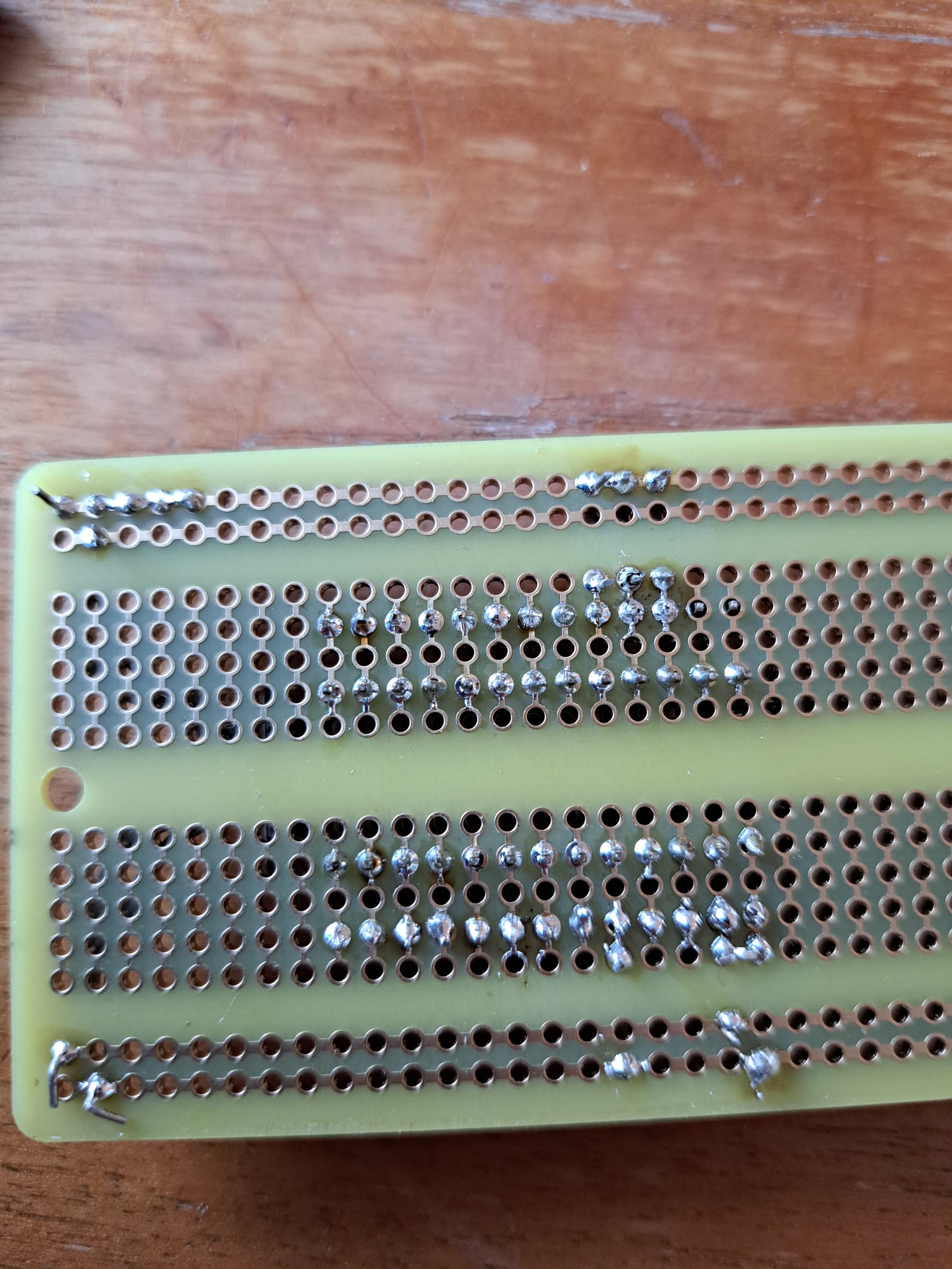
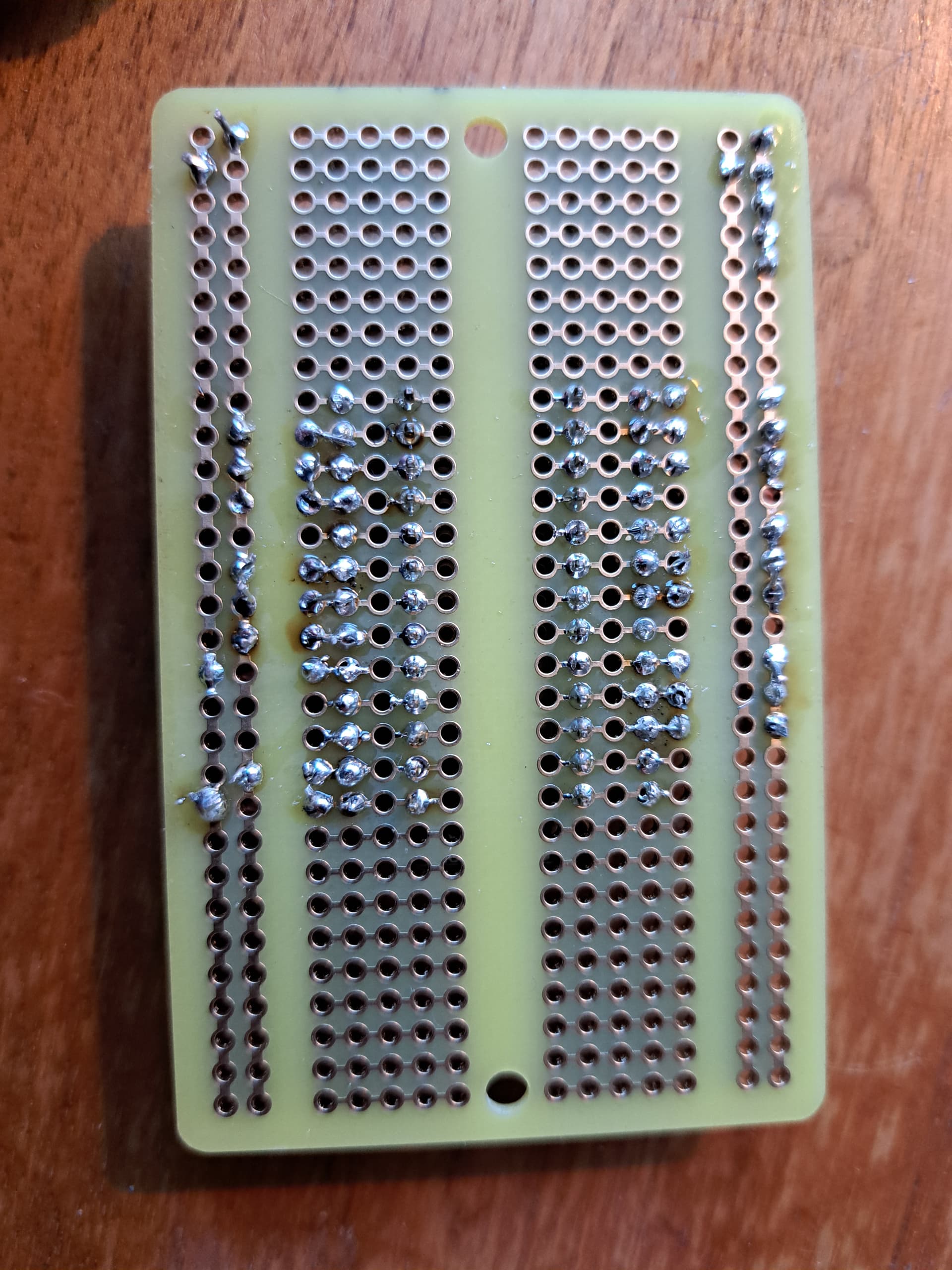
You’ve got two pins missed on the top row viewed from the bottom, and there’s a solder bridge on the same line of tracks on the lower side.
Probably a good idea to trim off the wires on the rails as well. they could easily short out.
Check over with a multimeter if one is available. Electrons don’t look at pictures, they just follow the electric field.
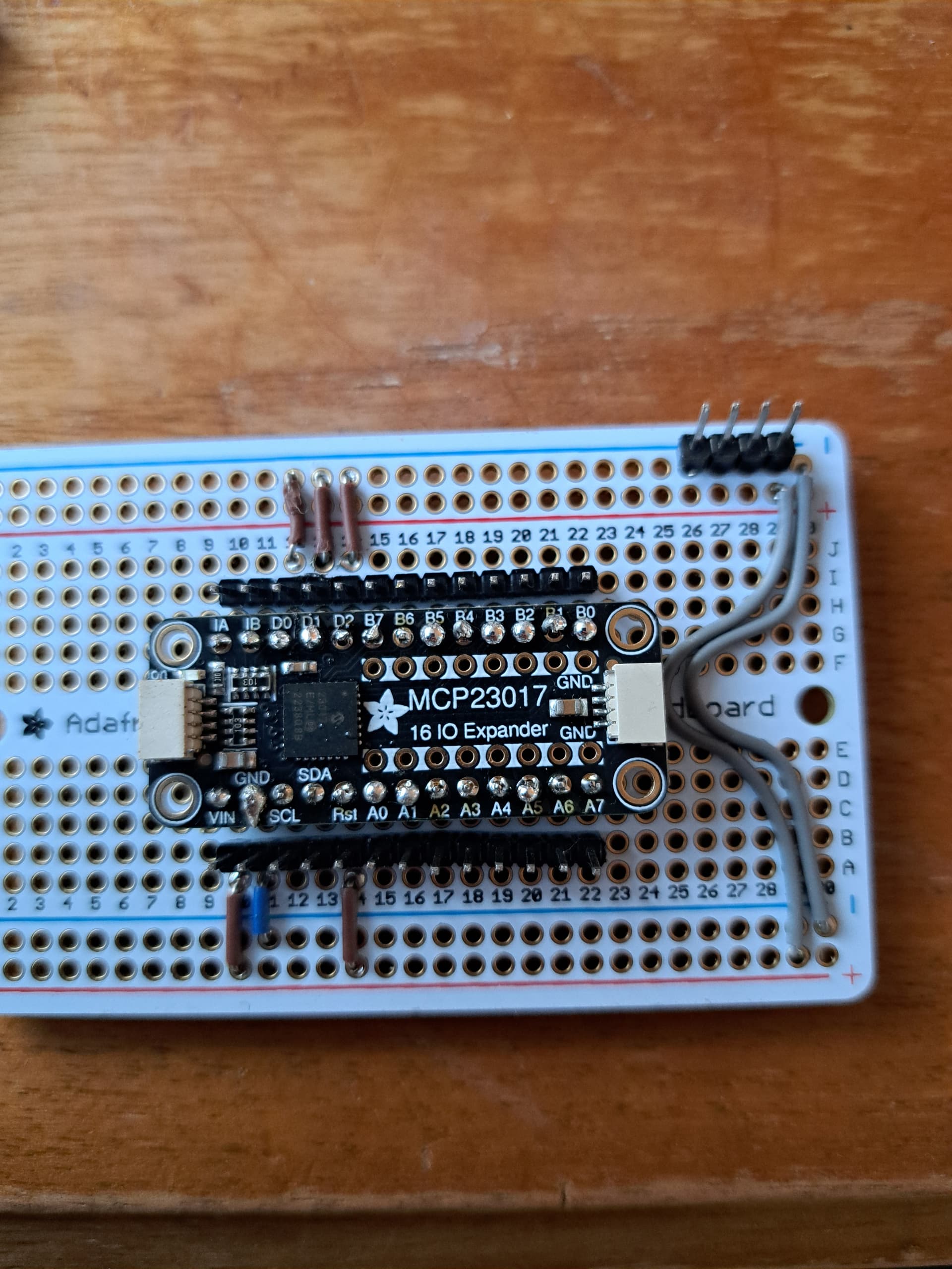
Looks ok. But always sanity check for a short across Power supply pins before plugging in. If you get a low reading, turn the probes round, the odds are you might have briefly kicked the chip into life with the resistance test. But it will be a high value the other way round.
Do you use flux?
It’s kind of essential with modern PB free solders. It cleans the surface and moves any grub it finds to the surface under surface tension and makes for clean solder flow.
No, I just use a basic iron and solder with colophonium included.
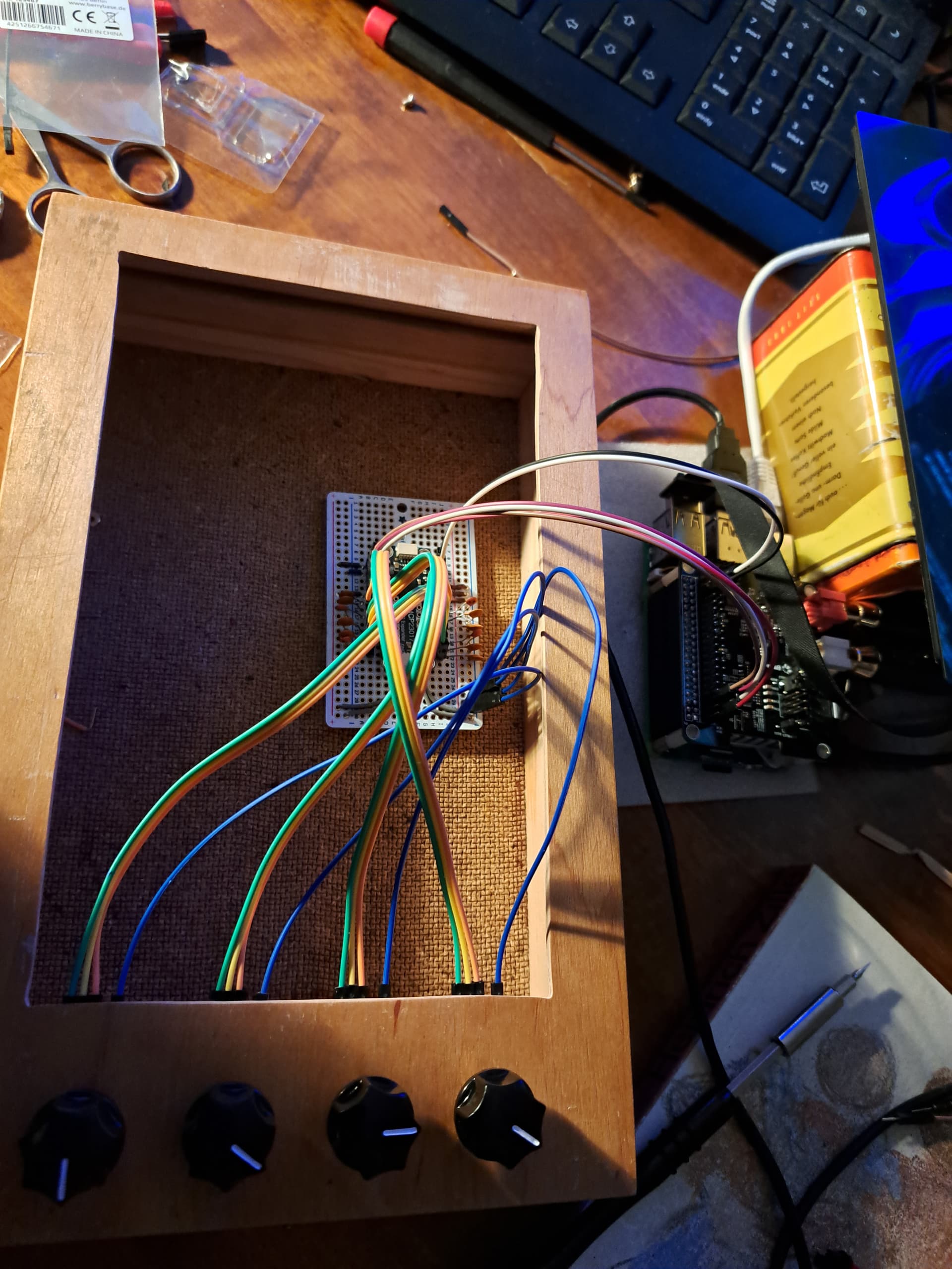
I fired it up. Knows are more or less functional:
- some encoder increment by 0.01 and decrement by 0.001
- Some inc/dec moves trigger occasional switch action
But the connections seem to be at least a at the right place
I have a multimeter, but I don’t know how to use it.
It’s worth swapping the encoders around to see if the particular characteristics follow the Zynthian Function ( it’s at the 23017 end) or the encoder (it’s at the other end)
All in all it seems that inc/dec/switch are in the right place. But it seems I have some “crosstalk”
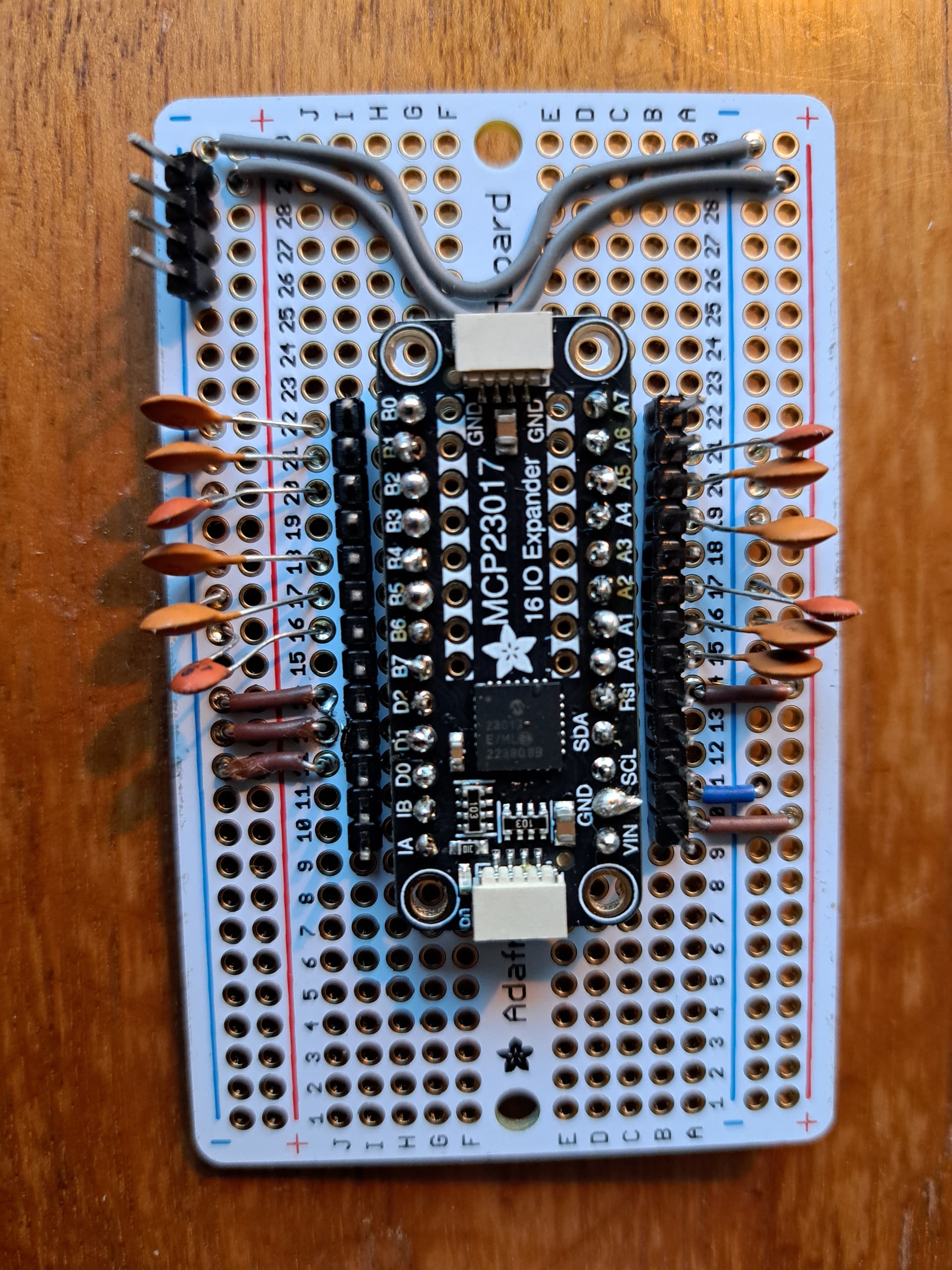
There are 3 resistors each in my encoders. Do these cause the above mentioned issues?

Maybe this post is related? Post
This is where the multimeter comes in handy.
You want the resistance switch setting on the multi meter and better still continuity which will produce a buzz when the two probes are connected.
I would suspect they are connected to the +V pin on the encoder and as a result with this pin disconnected they will all be interconnections between the three switches. If you an check continuity with multimeter, confirm that this is the case, ie. all the resistors are connected at one end and this goes to the +V pin and then check it the other side of the resistor is connected to the other pins.
I don’t know if that is specifically producing the result you are seeing but it certainly seems a possibility. Taking an encoder out and a good visual inspection will also tell you what is going on.
Personally I would remove them, but give them a good check and going over before trying it. Resistors between the switch pins and the encoder pins could certainly behave like this.
They should respond to gentle soldering iron attention, and it does sound like that post had a similar problem. I’ve not used one of these encoders so I haven’t actually tried to fix this.
1 Like
Well, reading that post it seems connecting all encoders V+ to my V+ line may then solve the problem as well? @riban, you think that would be the case?
Visual inspection shows the resistors are between encoder and switch pins on on side and V+ onthe other.
You shouldn’t need to.
There is a pull up resistor that is configurable at the "£017, and this is enabled in the zynth.
This is a resistor that is turned on in the chip in the same fashion as the pull up resistors mentioned in the i2c discussion.
The idea is if the pin in’t connected to anything then the pull up resistor ensures that it is set to +V , a logic high. When the switch or the encodrs make a connection they pull that pin low and that is what the zynth expects so you shouldn’t need to suppy +5V to the encoder. THese boards are designed for situations that don’t have the pull up resistors on the connected circuitry and want to have an emphatic +5V or OV from the board. The sort of things that go inside industrial control panels. IT should all work with just the encoder, but the resistors between the pins could certainly make them marginal in this circumstance.
@riban will be along shortly to tell me I’m talking rubbish once again. He enjoys doing that.
The idea to follow the suggestion connecting the V+ pins is attractive since this is less descructive than “cut the lines”. On the other hand I was soldering the first time in my life today and all the other things I did with your kind help were also premiers, so my problem is I don’t know how to unsolder the pcb from the encoder without having 5 irons in 5 hands.
Try adding the +V wire and see if that addresses the problem. That way you haven’t anything destructive to do. Just add 4 wires.
It saves you from the de-soldering that I’m sure is pretty intimidating.
See if you can measure the value of the resistors as a multimeter exercise.
10k each.
Don’t worry if it works with the +5V you will not think about this feature whilst you are using the thing in anger…
I use 3.3V, is that a problem?
Probably better to use the same +supply supplying the 23017 or are you driving that from 3.3V volt as well…?
either way the 23017 will expect to see whatever is on it’s +V connection to be truly happy.
I tried both, but sticked to 3.3V
Did it get any better?