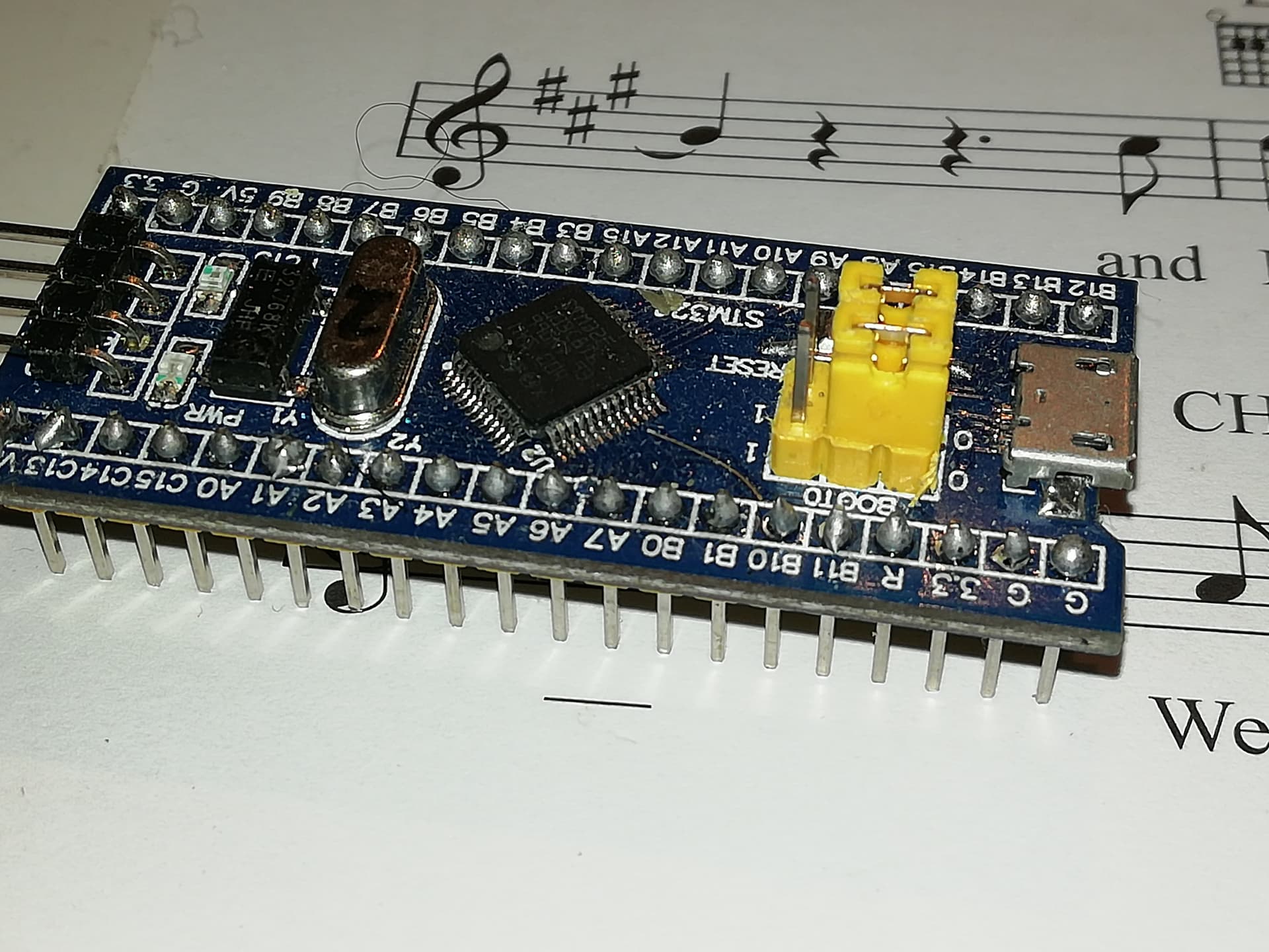
Here’s a similar blue pill notice the soldering on the pcb to connect the yellow edge connectors to the board. The difficult buy is that if you do solder them on you will have to then put them into a socket on strip board to mount it in your final device when you move off the breadboard… Don’t try and un solder them. It will not end well… The other option is solder wires to the holes in the 23017 board and then you have to workout what to do at the pi end… Possibly the easiest solution is do it with a disk drive connector as I did on the picture of the little black box and encoders I did in the picture above… Plan it a head of time…
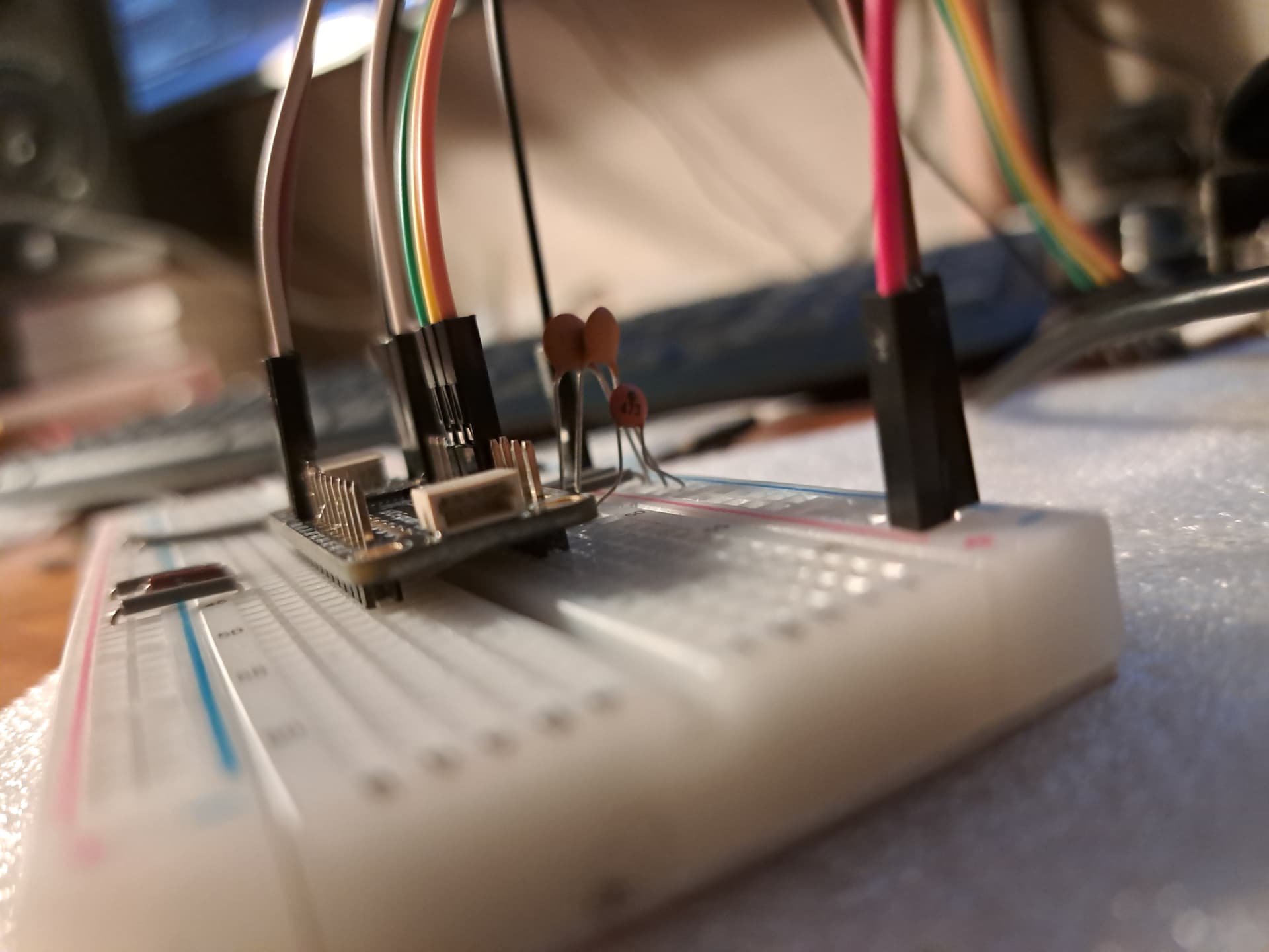
There aren’t too many wires going to the Pi from the 23017 board…
1/ OV
2/ + 5V
3/ SDA
4/ SCL
5/ INT 1
6/ INT 2
so you might get away with socket pins on the Pi end and soldered wires at the 23017 end. But remember the lengths of the wires as it’s easy to end up with something tht doesn’t fit if you cut a wire too short or something messy and unwieldy if you make them too long…
something like this…
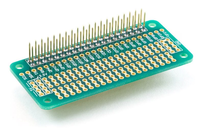
May be the way forward.
…Do you know how many times I’ve reflashed? ![]()
No surprise, I’m not so good at the soldering iron. I’m rather the acoustic guy. Goggling for remove solder stuff.
A piece of stranded copper wire is good for removing solder bridges.
Visual inspection, then multimeter, and patience.
Another important and useful thing isto make sure the workpiece is solidly mounted.
(venv) root@zynthian:~# i2cdetect -y 1
     0  1  2  3  4  5  6  7  8  9  a  b  c  d  e  f
00:                         -- -- -- -- -- -- -- --
10: -- -- -- -- -- -- -- -- -- -- -- -- -- -- -- --
20: 20 -- -- -- -- -- -- -- -- -- -- -- -- -- -- --
30: -- -- -- -- -- -- -- -- -- -- -- -- -- -- -- --
40: -- -- -- -- -- -- -- -- -- -- -- -- -- -- -- --
50: -- -- -- -- -- -- -- -- -- -- -- -- -- -- -- --
60: -- -- -- -- -- -- -- -- -- -- -- -- -- -- -- --
70: -- -- -- -- -- -- -- --
Good start.
The one encoder is moving and clicking as intended. I think I’m dreaming. This now without the Hifiberry
Edit: Works also on the hifiberry.
OK, I’ll move that to permanent. Now I have some questions:
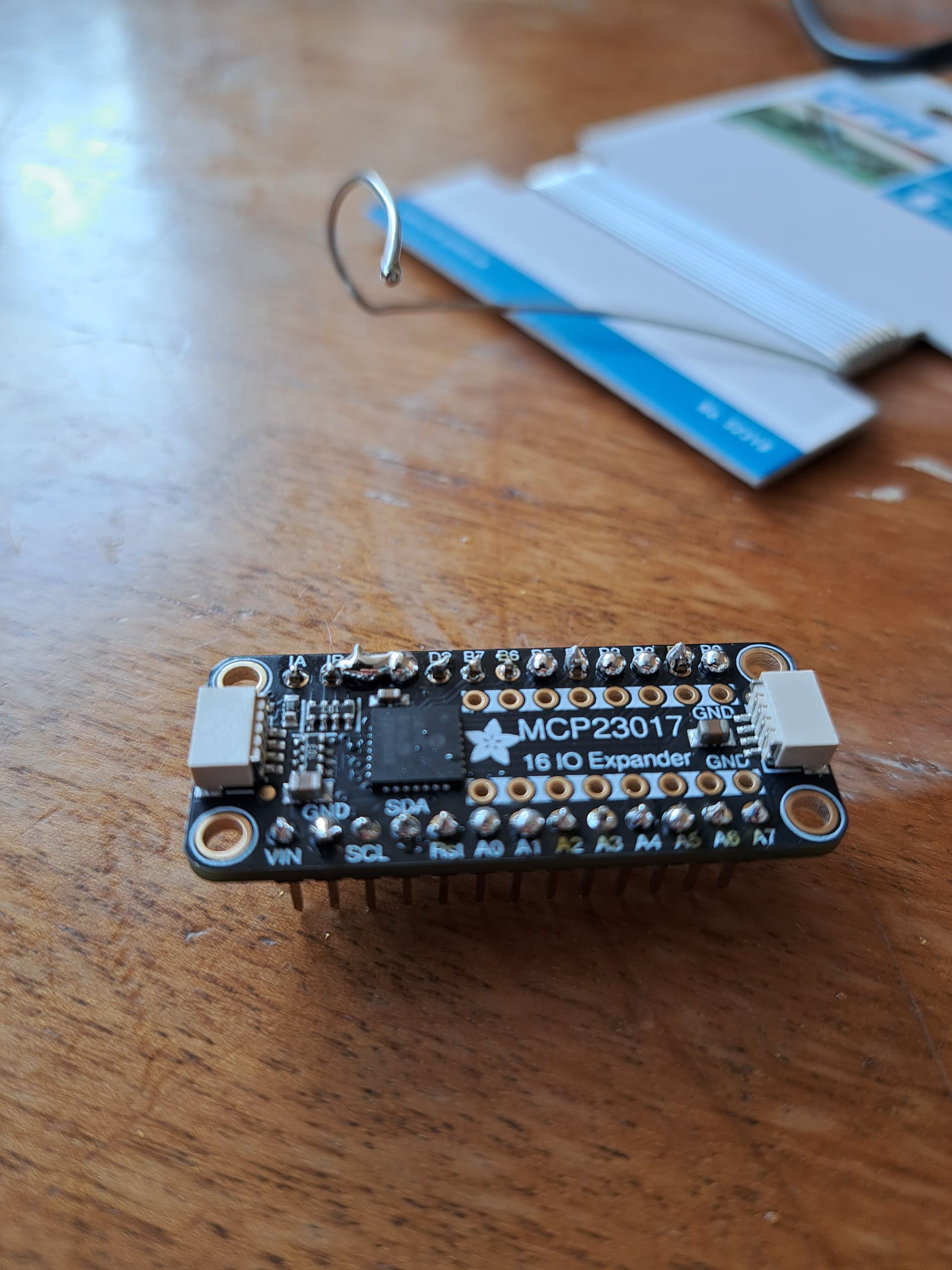
- I’ll solder the MCP permanently.
- I have some of these (Dumont?)-cables in m-m, m-f, f-f combinations. Should I solder them permanently with mal, or should I solder a oin header onto the board for dynamic exchanging?
Sorry: I forgot about the most important thing: THANKS for your patience!
Don’t solder on to anything that looks like it should take a connector unless you absolutely don’t want to take it apart at some point. As you put things into cases such options can get increasingly involved.
inter board soldering is really a last option, if any form of connector is available. It will make Pi 40 pin connectors pins very difficult to put a hat connector on later, for example.
Stripboard is quite good for mounting boards with pins on because you can simply put matching sockets on to it. Remember , of course, to cut the tracks between the row of pins, and check that they are all cut with a multimeter.
You can get a 40 pin connnector onto stripboard but you have to cut the copper tracks between the holes on the board, which is possible but rather more involved.
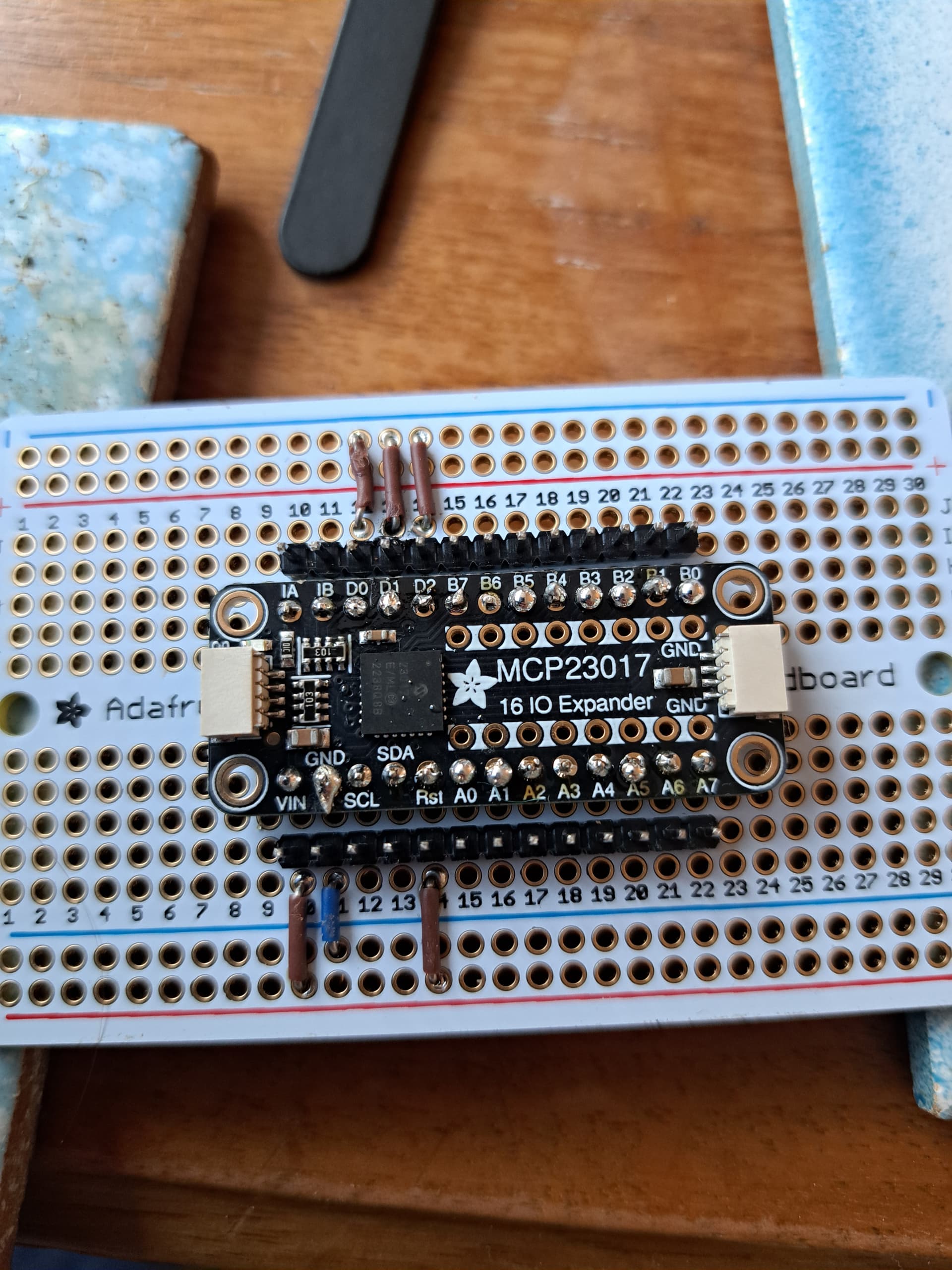
Excellent, well done. Just for information how are the A0,A1 & A2 pins connected.?
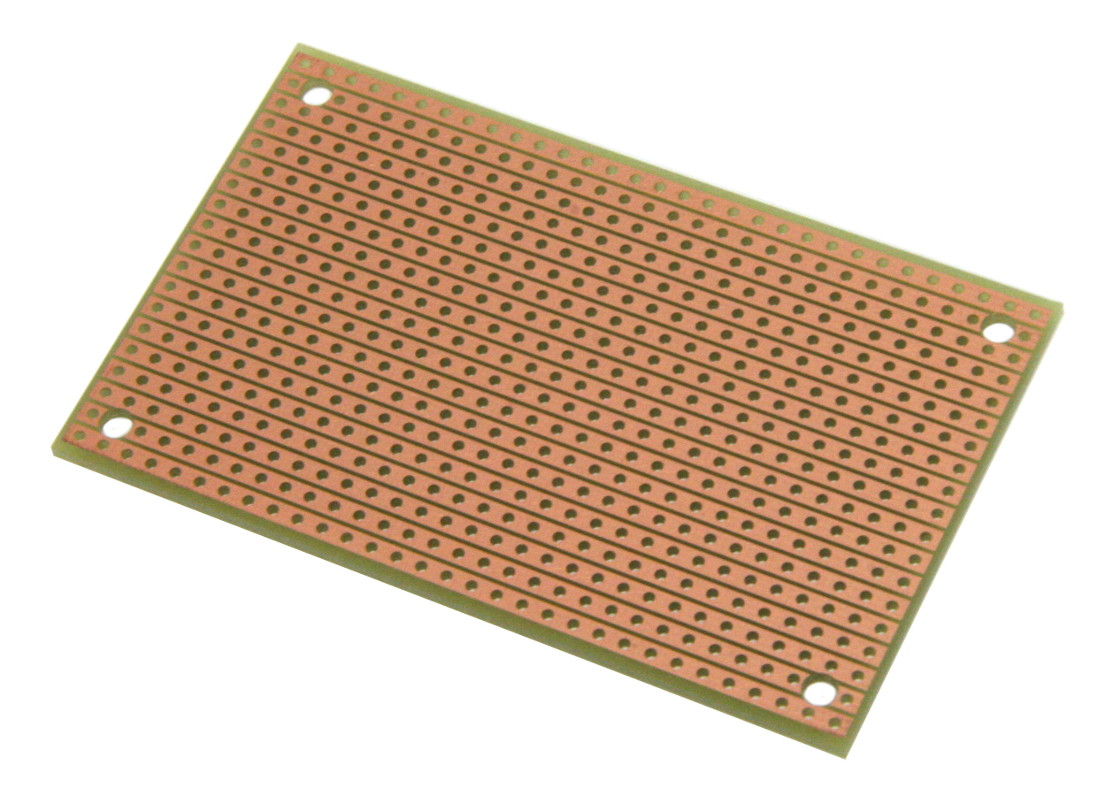
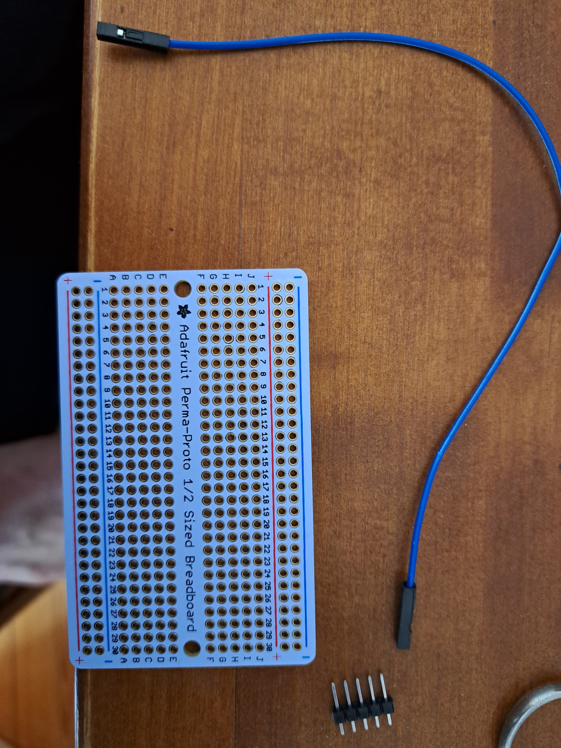
I don’t intend to solder anyhing onto the pi. I have a adafruit perma-breadboard I want to use. I just think about soldering these dividable pin headers for use with female-female dumont cables.
You know, these pin headers soldered on the board and connect these cables dynamically
All to GND. That’s what makes it 0x20. From what I understand is you use them as binary code (A2:A1:A0) so that GND:GND:GND equals 0x20 and V+:V+:V+ equals 0x27 and GND:GND:V+ equals 0x21
I don’t know the technology, but test it and assure yourself of it’s suitability.
It will make for a bit of a rats nest inside the box, but you can be much neater on the encoders, because you are repeating a design.
Time perhaps, now you have achieved 0x20 enlightenment, to consider the design in the box you intend to put it in.
It’s frequently a good idea, when doing this sort of thing, to alternate from top down views to bottom up.
Time for a picture?
p.s. Well done on the Soldering.
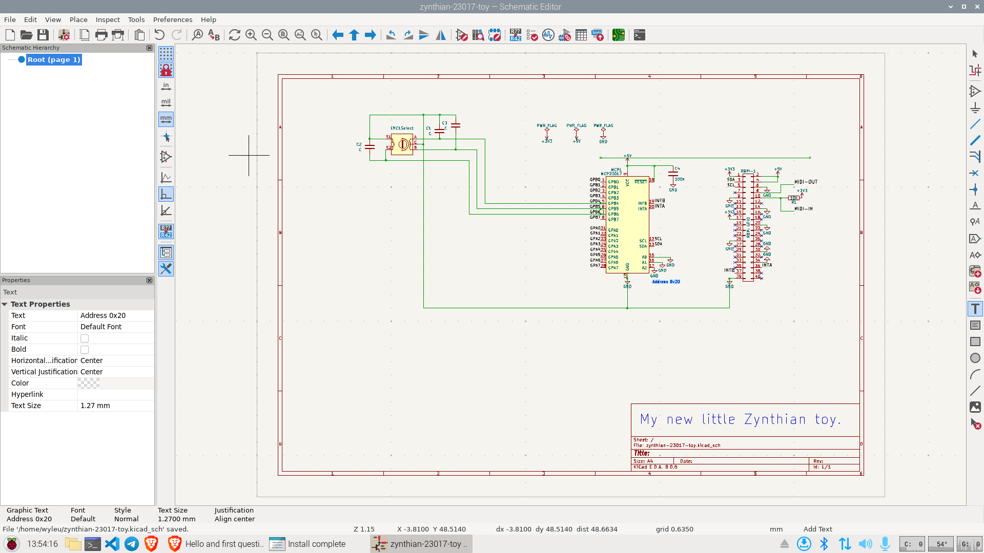
I’d provide any picture you want, but the design did not change from the start, it was all correct from the beginning.
Right so. we can move attention to the encoders.
Did you say you had run against zynthian?
Any select encoder switch action?
Yeah it worked
Right then.
That looks like a working solution!
When do you drill the holes in the Box?
Very last step