Hi all.
I have a custom Zynthian with a 3.5 inch screen attached to the GPOI pins. There are some pins free and I was wondering if it was possible to control the UI with switches connected to the remaining GPIO pins?
Kind regards
James
Hi all.
I have a custom Zynthian with a 3.5 inch screen attached to the GPOI pins. There are some pins free and I was wondering if it was possible to control the UI with switches connected to the remaining GPIO pins?
Kind regards
James
Hi,
All of this depends on your requirement and your setup:
I2S sound card use at least 3 pins
Your display use at least the SPI pins (19, 21, 23, 24, 26) + maybe some more for the touch screen facility
=> you’ll have to check that.
Midi In/out use pin 8&10
=> do you need midi IN/out (not midi over usb, but the good old one hardware midi)
and lastly, each encoders needs 3 gpio pins.
Just check it and if you think you’ll get enough free pins on RPI’s GPIO for the controllers, then with zynthian webconf’s you’ll be able to setup this quiet easily.
Feel free for more questions 
Hello
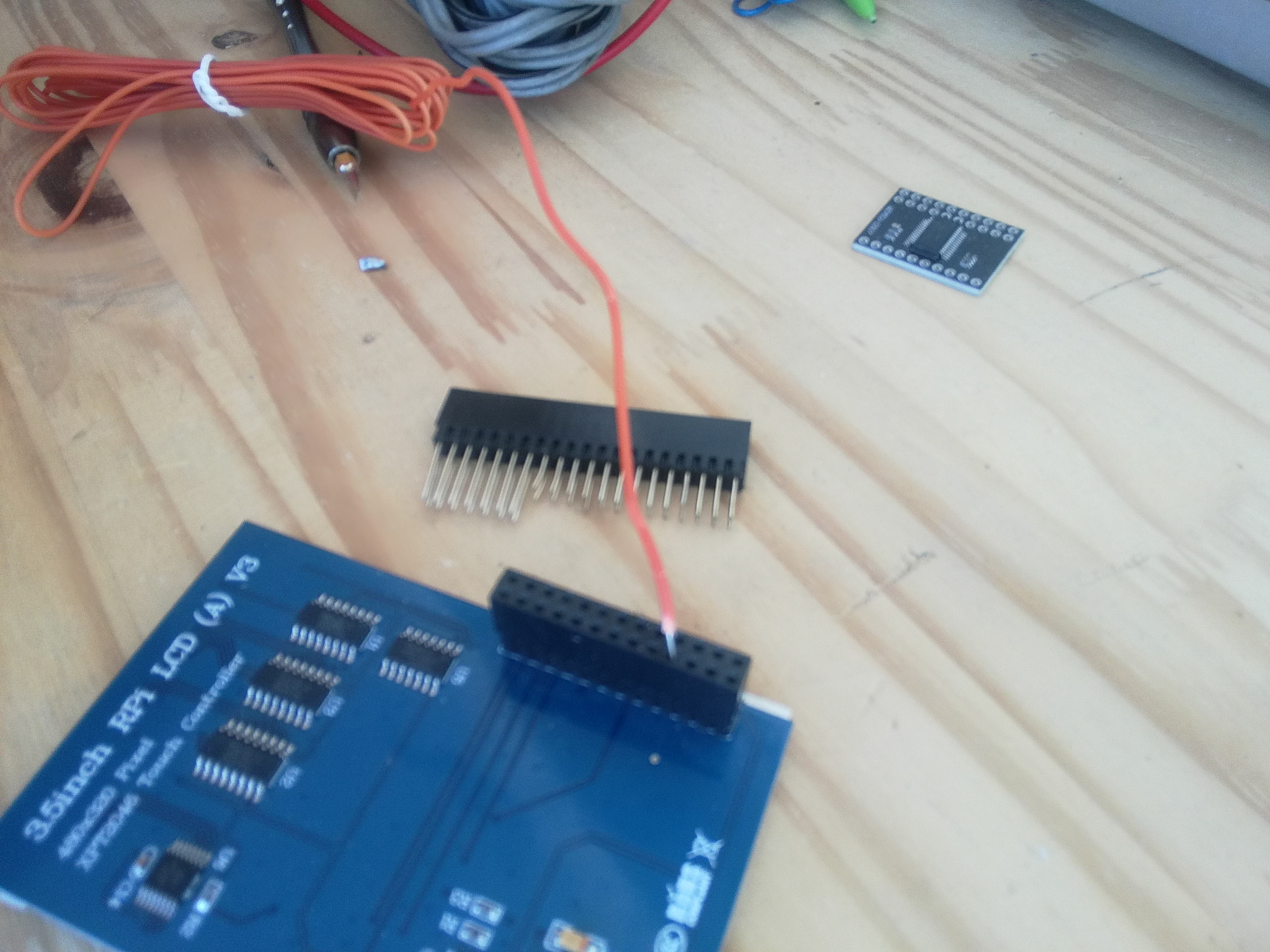
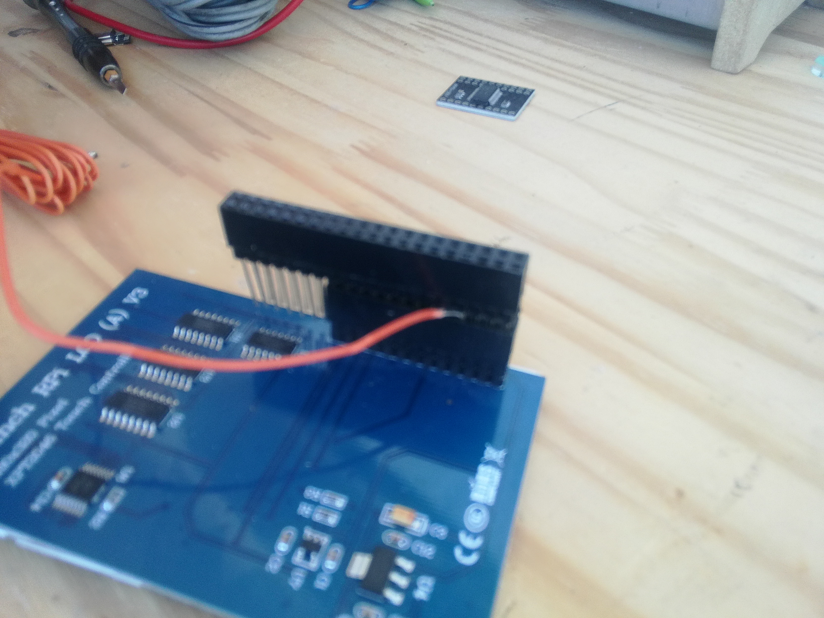
Thank you for your reply. Here’s a photo’s so you can see that I’m only using the Pins for the screen. Nothing else is connected to the remaining pins. I also use the Pi’s onboard sound, and I only use Midi over USB.
If I can use the remaining GPIO pins for navigating the UI, that would be amazing. I’ve had a look at the webconf but I’m not sure I understand how that can be used to assign additional function to control the UI from a switch connected to the pins.
Any help would be appreciated as it would save me a lot of trouble building my own solution using a Teency-LC.
Kind regards
James.
Hi again,
Ok, as is, they are only pins n° 29 31 32 35 36 37 38 40 available
they are not enough free gpio’s pins left for 4x3 the pins used by the encoders (4 of them are missing).
but if your feeling relax enough for some dirty hack, you can solder (or not) 4 of the unused pins (3, 5, 7, 10, 11, 12, 13, 15 eg ) that are covered by the display header directly to the encoder and then configure them using the webconf tool.
Thank you for your help.
I’ve no problem soldering if need be, but does it have to be encoders? Would it be possible to just use 2 pins per button for momentary switches?
Looking at the Webconfig, I don’t understand how this is meant to be configure.
I currently have it set to…
Custom Switch-1 Action:
UI Action
Short Push:
Select Down.
And I’ve changed the default Switches Pins values from this…
100,103,108,111,106,107,114,115
To this
36,none,none,none
Now when I short pins 34 (ground) and 36 together, nothing happens. Where I had expected to see it “Select Down”
Clearly I’m missing something. Any help would greatly be appreciated.
James.
Yes, I think that you’re doing it right.
I maybe wrong, but I don’t think this is working at all. I’m not getting a geek out of these pins no matter what I do. No midi notes, no UI changes. Zip.
I’ve even tried to switch to 2020-06-08 to see if that would make any difference, and that OS won’t even install. Same issue as reported in the thread here of not getting past the Error/IP splash screen.
https://discourse.zynthian.org/t/its-time-for-buster-rc-2-testers-needed/4202/60
Regards
James
that list is for wiring encoders on the mcp23017 port expander and works like this:encoder_1_switch_pin_number, encoder_2_switch_pin_number, encoder_3_switch_pin_number, encoder_4_switch_pin_number, custom_switch_1_pin_number, custom_switch_2_pin_number, custom_switch_3_pin_number, custom_switch_4_pin_number,
And I think (but not 100% sure) that you shouldn’t use the raspberry pin header number but the GPIO id (eg, for pin 36, GPIO 16)