Thank you tunagenes and Hans!
Yes, V5 assumes 0x21 for the encoders.
You don’t need the second MCP. It’s only for buttons, if you don’t use directly connected buttons you can leave it away. If you do use it, it has address 0x20.
2 Likes
Hi again,
I have summarized my errings in a PDF on GitHub - jean-claudeF/synthesizer: Synthesizer experiments
Maybe it can help others to not make all the mistakes I have done.
If something important is missing, please tell me, I’ll add it.
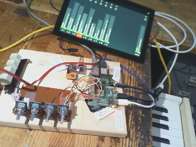
By the way, I have changed the big monitor for a touch screen from Admatec I had lying around, and it simply worked. Linux is lovely! Zynthian is lovely! ![]()
![]()
2 Likes
Next step will be to add more buttons. But as my character is as it is, I will try to recycle buttons I have in my stock. And to do it well, I’ll first have to study the philosophy of using Z.
2 Likes
Hi Jean-Claude,
Wonderful that you succeeded in finally making the encoders work!! ![]()
And… very nice for all that probably will encounter the same kind of issues as you (and me too!!) that you documented your learnings here at Git (Perhaps a link from the Zynthian WIKI?) ![]()
Hope you have a great time making music woth the Zynthian!
Cheers,
Maarten
1 Like
Looks promising!! ![]()
You also made some music?
(I always loose myself in drowing in all technical possibilities… is stead of creating and playing music…)
Cheers,
Maarten
4 Likes
That’s exactly what’s happening to me!
It was already so around 1975/76 when I built my first analog synthesizer.
But as I love electronics I don’t see this as a big problem. If so, I would have bought a Zynthian kit!![]()
1 Like
I’ve been lurking around here a while and have made a few on-and-off attempts at getting encoders working over the past couple of years - between this thread and the wiki page I’ve finally got there, and met many of the same hurdles discussed here (encoder type and the “custom” profile not working being particular sticking point). I wanted to share my appreciation for your help! Now to write some notes…
As seems to be a common problem, I had encoders with V+ rails. I think it has been mentioned elsewhere, but in case anyone else stumbles across this - I managed to make them zynthian friendly by desoldering the 10k resistors that connected the two encoder pins to V+. Then the encoder A&B, switch and ground pins should not have continuity when probed with a multi-meter.
My next steps are going to be tackling MIDI ports and the 20 button array found on the V5, so I will need an additional MCP23017 (or two?). The web conf doesn’t allow selecting MCP addresses or int pins for the multiple chips though - are there specific i2c addresses & GPIO pins that subsequent chips must use? Also, I the first chip only started working when I used the “MCP23017 Encoders V5 Touch” profile - Is this the profile to use when connecting multiple MCPs?
Thanks again for all your collective help (and for sharing your notes repo JC!). I’m very glad to finally have a working prototype, and to be one step closer to getting this thing off the bench!
2 Likes
Hi clmain,
I can feel with you…
Some of my most important thoughts to this:
-
the encoder type is OK, when it has pullups on its own they MUST be connected to +3.3V
Or you desolder them, that’s OK too. -
I lost most of my time using “Custom” wiring as it seemed logical to me.
You are right, “MCP23017 Encoders V5 Touch” is the one to choose.
What I also didn’t know is that the version number has nothing to do with the Raspi version.
So V5 is OK also for Raspi 4. -
As I understand it, 0x20 is for the first MCP, the next one is automatically 0x21
Am I right ??? -
What helped a lot was the schematic V5 Control Board “hidden” in plain sight in the hardware Github page.
-
The functionality of the V5 version encoders is very different from those of previous versions.
Happy building!
1 Like
Hi Jean Claude,
On the MCP23017 you have to select thd adress… If you do nothing the adress is 0x20 if you solder A0 to +V then it is 0x21…
So not automatic on tge board except for the first one and of courss select in webconfig page the correct adress. So if no slodering then select 0x20.
Cheers,
Maarten
Sorry… looking at the documents you made… redundant information…
Enjoy your day!
Cheers,
maarten
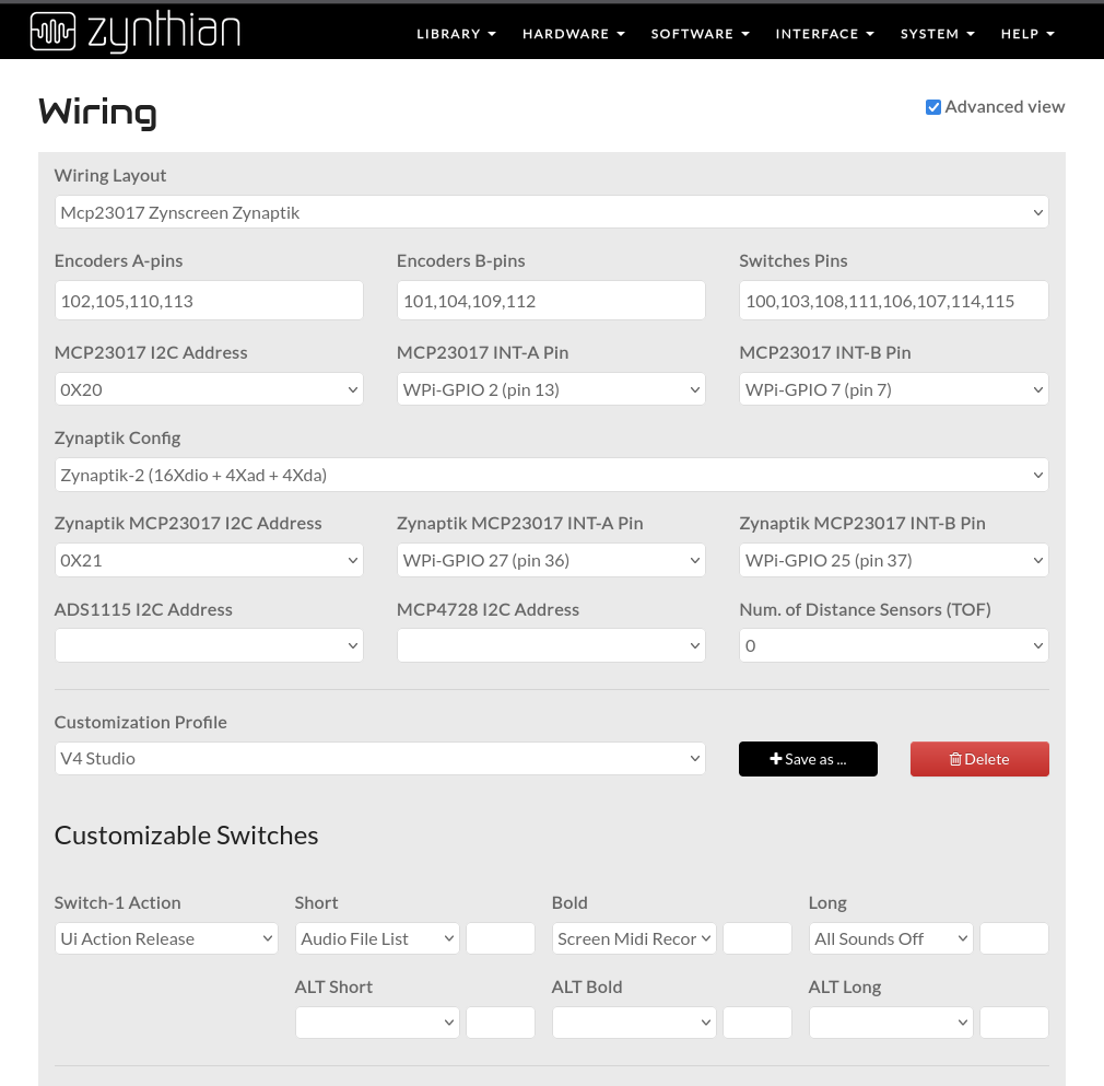
Hi @Jean-Claude_Feltes and other zynthianers fighting with custom wiring layouts,
I’ve fixed webconf configuration so “custom” wiring should now work OK.
Also, i’ve added config options for the zynaptik’s MCP23017. This will allow to configure the 2nd (or third, for V5) MCP23017 chip that was hardcoded to 0x21 until now.
If you test, please give some feedback.
Regards,
1 Like
Sorry that the info is redundant. How could it be different as I gathered everything from the forum and my experience. I hope however that it is a sort of summary of our discussion.
And, to be honest, it is also a summary for myself.
1 Like
Hi Jean-Claude… I meant… MY info is redundant…
Sorry for the misunderstanding… ![]()
Cheers,
Maarten
No problem! ![]()
Thank you jofemodo!
3 Likes
Important info for those who, like me, use an MCP23017 in DIL package:
The pin numbers are different from those of the SMD package, that is to say for the schematic on Github.
2 Likes
I have my 20 knobs and 4 encoders attached now. The schematic is that of V5_main, that is to say
-
buttons SW11 to SW44 on U1, the top MCP23017 (address 0x20), with
INTA = INT1 on RPi4 pin 29 (GPIO5),
INTB = INT2 on RPi4 pin 31 (GPIO6), -
4 encoders with their switches pot1_sw to pot4_sw and buttons SW51 to SW54
on the bottom MCP23017 (address 0x21), with
INTA = INT3 on RPi4 pin 11 (GPIO17)
INTB = INT4 on RPi4 pin 13 (GPIO27)(All Rpi pin numbers are physical pins)
That’s all I have for now, plus a touchscreen and a PCM5102 audio DAC that works with HiFiBerry DAC+ setting.
Sound is working, Ihave still not succeeded in getting the buttons + encoders to work.
Must control the wiring, there are so many possibilities to do wrong, especially as the numbers are confusing (physical pin, GPIO, Wpi…)
If I understand well, this should run with wiring profile V5 (it doesn’t), or is it V5Zynface or MCP23017 V5 Touch?
It’s quite confusing!