Config info for custom wiring

I localised the code generating these error messages now in zynpot.c:

int setup_behaviour_zynpot(uint8_t i, int32_t step) {
if (i>MAX_NUM_ZYNPOTS || zynpots[i].type==ZYNPOT_NONE) {
fprintf(stderr, “ZynCore->setup_behaviour_zynpot(%d): Invalid index!\n”, i);
return 0;
}
return zynpots[i].setup_behaviour(zynpots[i].i, step);
}

Looks as if MAX_NUM_ZYNPOTS was not set or the type is incorrect.

You are digging way too deep. You are not pursuing a bug in the zynthian code as this code has worked reliably and consistently from the early days, you have almost undoubtedly mis-configured your set up or have a hardware issue that is blocking functionality . Start simplistically in webconf and build from there, and if you can get hold of the simpler form of encoder that will mean we will be comparing like with like.

It genuinely isn’t helping that you are using encoders in a non standard zynthian way. For instance have you checked that your +V lines to the encoder array aren’t shorting out or something similar?

Without having your installation in front of us, and given you are using a non standard configuration it’s hard for us to suggest where your problems lie and the solution is almost certainly not going to involved alteration of core coding elements.

Could you supply us one or two pictures of the installation?. I tend to suspect hardware first and you have added the complications of power supply components to the rig. Encoders are notorious for short interconnections, indeed a test of a good encoder is to put a continuity tester across pins A& B and rotate the encoder. You will here short beeps as the two tracks align. This can be enough to confuse devices, especially if there are solder bridges or shorts present.. I’m not saying this is your problem but it is indicative of the kind of things that can happen.

But getting one encoder working with switches and rotation is a great confirmation that things are correct and the Select encoder is the obvious one to target.

2 Likes

Sorry, but I have developed this character feature during the years. As a child when something went wrong, I would throw everything away. But slowly I learned that didding into the deep is sometimes painful, but at the end always rewarding. If you go on.

You won’t convince me so easily that the encoders are the problem. Yes, VCC is OK, the signals seem OK on the osci.

”You are not pursuing a bug in the zynthian code as this code has worked reliably and consistently from the early days”
I never thought there is a bug in the code!
No, I think there is a bug in my understanding of configuration. That’s why I try to find out.

Hi @Jean-Claude_Feltes .

I don’t think @wyleu means the encoders are the problem. At least I am not. What we want to tell you is that your way of using them is not the zynthian way. Of course you can keep digging, but it would be much quicker (and better for learning) if you do one step back and start with a situation that will most likely work.

My suggestion:
Buy one of these encoders for € 1,50
Connect power (3.3v is ok)
Connect S1 and S2 to the expander ports GPB0 and GPB1
Connect Key to GPA0
Revert all your config changes to default
Test if (and until) the encoder works.

Big advantage of this device is that the contacts are well defined and there are pull-up resistors and decoupling capacitors on board.

When this works, you can start fiddling with your own encoders and deviating port numbers.

It would save you and us a lot of time.

Kind regards,
Hans.

1 Like
”What we want to tell you is that your way of using them is not the zynthian way.”

The whole time I have asked what is the zynthian way.
My problem is: I found nowhere the explicit rules of configuration.
My guess is that I am missing some important part of information that is clear for all of those who have had success, and for me it is lost in the hundreds or thousands of documents, wikis, and forum items.

Concerning the encoders: I am not opposed to use encoders that are better maybe. Why I suppose there is a config problem: at least there should be a sign of activity, and no error message at the start without even turning the knob.

”Connect S1 and S2 to the expander ports GPB0 and GPB1
Connect Key to GPA0”
Revert all your config changes to default”
What is the default?

For this 1 encoder I see the config like this:

Am I right?
What I’m not sure about is this:
Wiring Layou: Custom
Zynaptik Config: Custom 16Xdio
Customization profile ??

I suppose with one of these I have a misunderstanding.

Anyway, I want to thank all of you who have tried to help me!!!
You are a big support to me and I hope that once I can give something back.
:star: :star: :star: :sun: :sun: :sun:

Happy new year and a lot of music for all of you!

1 Like

I guess you encountered a less pleasant part of the zynthian way :wink:

I am working on a DIY Zynthian, mostly for experimental features that I don’t want to use my kit for.

What I have done is select wiring layout V5:

You don’t need a complete V5 for this to work. I have no buttons directly connected, but use an USB keypad.
But I do have 4 encoders (the same type I mentioned in my last post) and I connected them as indicated in the V5 schematic:

I also used an MCP23017 PCB:

I’m used to making everything myself from bare components, but this time I didn’t feel like doing all that soldering work so I chose the easy way.

Normally I have to do these encoders at least twice because I mistakenly changed wires. This time it worked straight away and it also looks much neater.

btw, if you go this route, don’t forget to remove the zero ohm resistor from A0 to GND and put a solder blob to VCC to choose I2C address 21.

Kind regards and best wishes to you too.
Hans.

1 Like

Hi Jean-Claude,

First of all: Best wishes (you need them it seems :sweat_smile:)
Also best wishes for everybody that works together in this incredible Zynthian world!
:folded_hands::folded_hands::folded_hands::folded_hands::folded_hands::folded_hands::folded_hands::folded_hands::folded_hands::folded_hands::folded_hands::folded_hands::folded_hands::folded_hands:

I am just following the law of entropy and add my configuration with the content of the configuration page in zynthian; Perhaps more chaos makes the chance bigger to find some fixed structure :slight_smile:

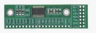
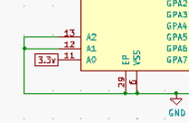
The hardware: You see the adresses I used in the configuration page written down in pencil on the hardware sheet. (NOTE: the adress of the MCP23017 is left at 0|0|0 So no soldering :-))
IMG_20260103_0001_1P.pdf (754.5 KB)

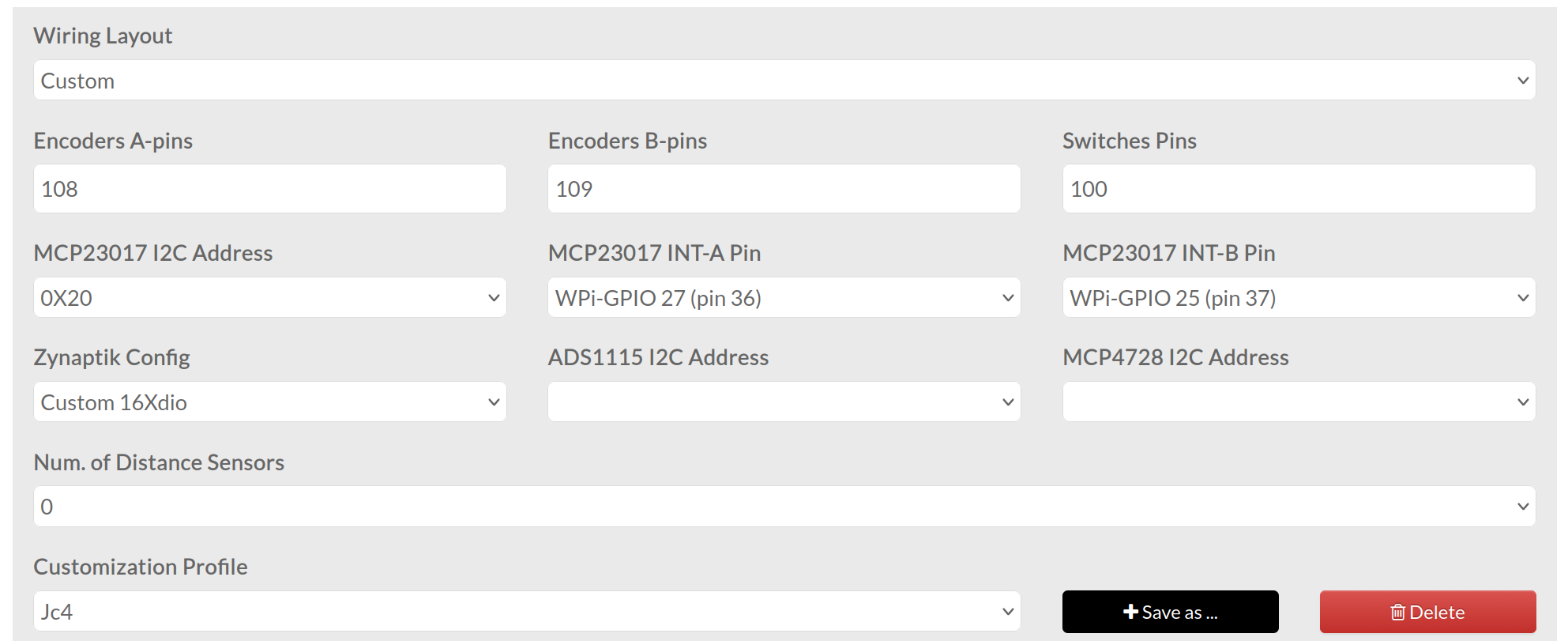
The Configurations screen in the zynthian web interface:

The Switches Pins are not all visible so: -1,-1,-1,-1,-1,-1,-1,-1,-1,-1,-1,-1,-1,-1,-1,-1,-1,-1,-1,-1,-1,-1,-1,-1,104,105,106,107

I use the template for the software button version (Thanks to the great support of @wanthalf (Pavel) and of course @riban and @ jofemodo and others)

This configuration works :slight_smile: (needless to say! :rofl:)

Succes and hope you will be able to enjoy the Zynthian!

Cheers,
Maarten

Thanks a lot , Hans and Maarten,
it was this kind of info I was looking for.
I will try it in the near future.

Yes, it seems I do it the hard way.
Like this I’m going to be an expert, haha :slightly_smiling_face:
(as an expert is someone who has done every imaginable error in a certain field.)

Haha, I think you are right @maartmaart !

Just out of curiosity (that’s the advantage of having an experimental Zynth) I used your wiring settings, with only one change, my MCP23017 I2C Address is set to 0x21.

And guess what? It works!

So apart from the MCP23017 address you have accurately described the V5 layout!

Perhaps that is also of use for @Jean-Claude_Feltes, at least it is good for my own understanding :grin:

Kind regards,
Hans.

2 Likes

Let us know whether you succeed!

Cheers,
Maarten

Perhaps the adressing is related to the adress you have set on the MCP23017?

Cheers,
Maarten

Yes, it’s described in the MCP23017/MCP23S17 datasheet from Microchip. It is not very accessible and it helps if you have programmed PIC microcontrollers.

The Client Address is composed of 7 bits. Bits 6-3 are fixed 0100, bits 2-0 are A2, A1 and A0 respectively..

If you connect A2-A0 all three to ground (making them 0) then the address becomes:
0100 000 or 0x20.
If you connect A0 to VDD (+3.3V, making it 1) it becomes:
0100 001 or 0x21

So you can number them until:
0100 111 or 0x27

I hope I am clear.

Hans.

1 Like

Thanks Hans!!

Maarten

When I look at your schematic, I see that the encoders are connected to the MCP23017 with address 0x21. So when I choose V5 this is automatically assumed?

Do I have to use the second MCP or can I leave it away for testing?

Hi Jean-Claude,

The adress in de software depends on how you set the adress on the MCP23017 board… if you leave it … doing nothing at 000 tthen you have to choose adress 0X20…
So the adress can be changed… the V5 selection is just a kind of preset of which you can change individual settings.

Cheers,
Maarten

This is really weird and even more: enjoyable :sun: :slightly_smiling_face: :sun:!
I got a first reaction from my encoders.
@Chris: they do work (even if they are a different type)! :slight_smile:

The config is this

with swiches pins -1,-1,-1,-1,-1,-1,-1,-1,-1,-1,-1,-1,-1,-1,-1,-1,-1,-1,-1,-1,-1,-1,-1,-1,100,103,108,111
and with the schematic I posted at the beginning.
I wouldddd not have imagined that I have to select McpEncoder_V5_Touch, instead I always had “Custom” wiring as this seemed logic to me.

Now there are still 2 things that are mysterious to me:

  1. What is Customization Profile and

  2. Zynaptic Config ?

As I still had no time to look at the actions of my encoders (how they should act), I am really happy that I ave ANY reaction when turning the knobs :sun: :slightly_smiling_face: :sun:

Maybe you would like to have a look at my testing setup:

1 Like

Hi @Jean-Claude_Feltes ,

Congratulations! I’m glad you get at least a response.

On choosing a wiring layout in Webconf:
When I choose the @maartmaart Custom settings (MCP23017 Encoders V5 Touch) the layout of my screen changes, it becomes a V4 layout:

When I change it back to V5 it becomes a normal V5 layout:

So depending on the wiring setting, there are unexpected side-effects.
I’m going with the standard V5 wiring. That’s the best guarantee for staying in sync with the rest of the Zynthianers.

Kind regards,
Hans.

(OT: I have a passive cooling and the LED in the upper left indicates the CPU temperature. I just switched the device on and then it is green. When the temperature reaches 70 °C it is a fierce red but well beneath the throttle temperature. I have never reached this (only when running stress for 20 minutes). It only becomes orange (55° C) with demanding DSP563XX engines. However, it is not Barcelona in the summer. :sweat_smile:)

From January 2022 in this forum:

Zynaptik is an optional-additional board there were several versions. I don’t know the current status-availability of Zynaptik, but I think you can safely ignore it. This is from the wiki:

The zynaptik module provides:

3 x standard MIDI ports (IN, OUT, THRU)
16 x digital Input/Output
4 x Analog Input
4 x Analog Ouput

Here’s the wiki link: