Hello everybody.
I hope not to get in the way of the site, but I wanted to share this project … A usb / midi controller that you can TOUCH …
The project starts from this video on YouTube:
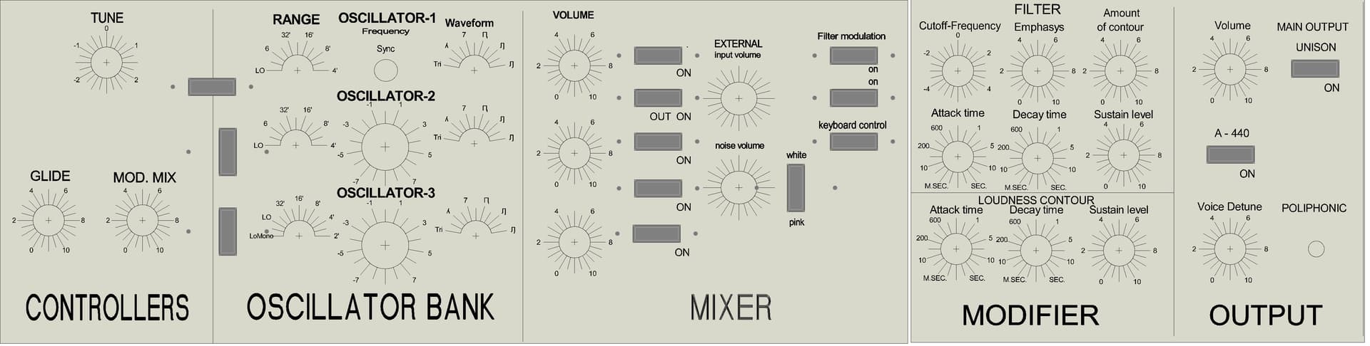
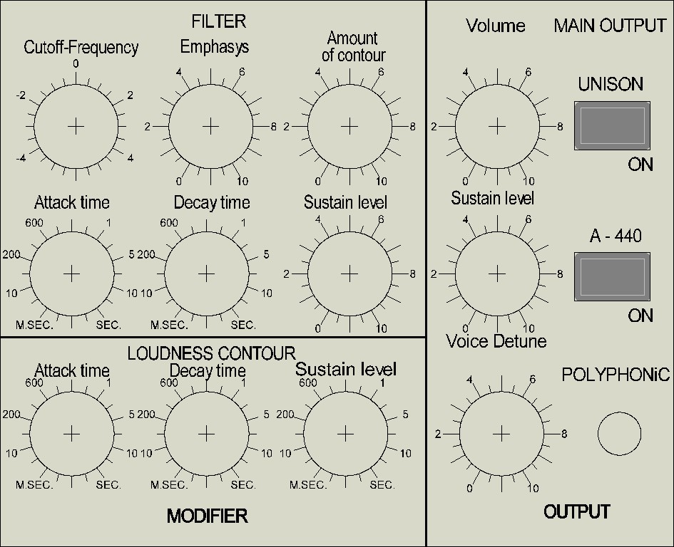
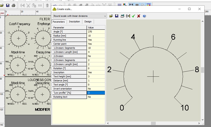
Today I am committed to designing a front panel that I am attaching. I used Front Designer 3.0.
Anyone who wants to improve my work is welcome.
Oops, yes, tired eyes made me wrong …
The led points are actually the holes to fix the switches that I found interlocking … I will eliminate the holes that I did not want to put … for the third oscillator I do not think there is enough space … you could put a switch / diverter to use OSC2 as OSC 3?
Yes that might be nice. A kind of alt function button.
I don’t know if Raffo Synth does this but the MiniMoog has a different waveform option on OSC 3.
For waveform labels, you may need to use images rather than text. I haven’t found any typeset with waveform images. Alternatively you could use abbreviations like tri, saw, etc. Not ideal!
Thank you so much Riban.
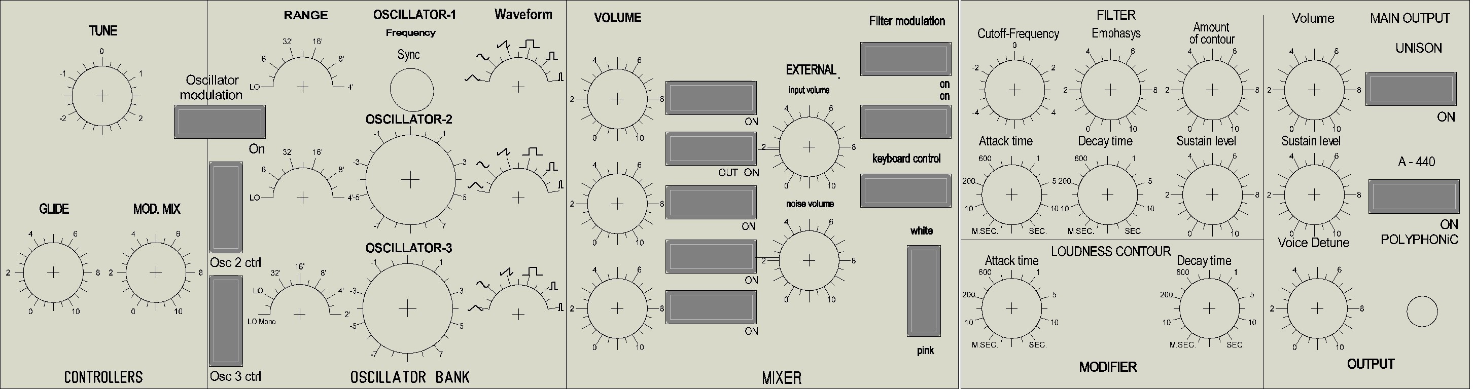
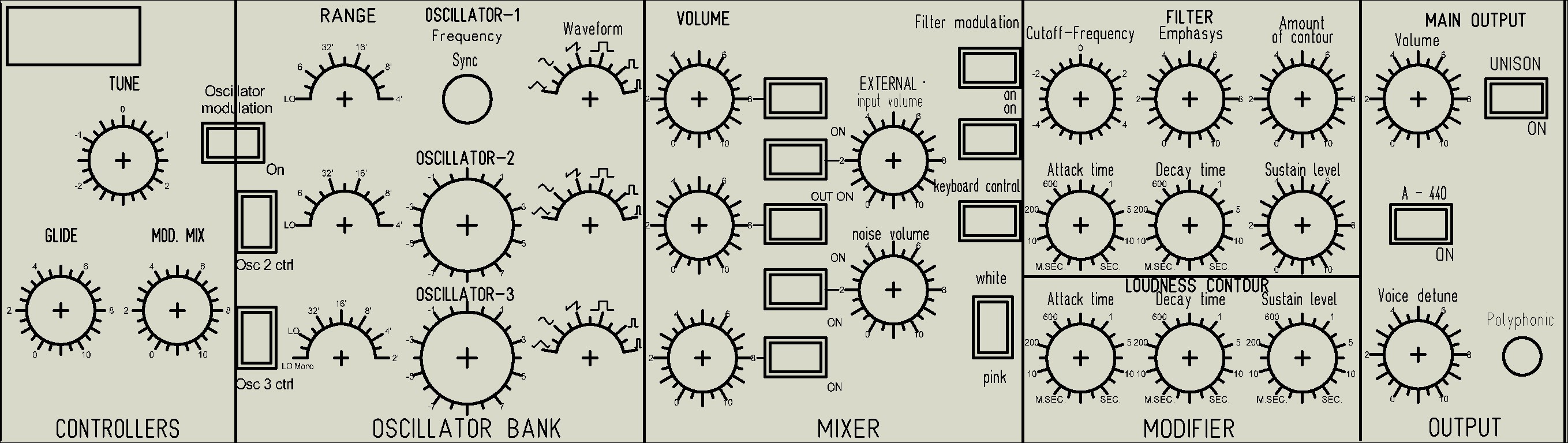
This is my second experience with this software and I’m certainly not a good designer … Then I realized that I had the wrong size … this was almost 80 cm wide … I redid almost everything … poor i My eyes…
I attach the result with the files to modify it and the new waveforms … I assume that the lambda symbol can be replaced with the sinusoid symbol … you will tell me … Thanks Frontale MiniMoog.FPL (164.6 KB) Frontale MiniMoog2.FPL (110.8 KB)
Big problem also the dimensions of the switches … I found these that resemble the originals but have engraved above 0 and I … and the dimensions are excessive … 30.4 x 11.2 the hole … If someone would help me to find smaller buttons, similar and that do not cost an exaggeration I could make the front smaller again …
Another information … on the Zynthian Raffo sinth, the range and the waveform could be controlled with a multi-position switch? because it would be more precise and more similar to the original panel …
Yes! The controller should send equally spaced values from 0 to 127 which should select the discrete values in Raffo Synth.
Have you tried Raffo Synth? I’m not 100% happy with it. I find it treats the sound as you adjust values and maybe had a less than authentic analogue emulation. Prove to yourself it is suitable before investing to much time.
I haven’t given it much time so my opinion may be unwarranted.
Raffo sinth doesn’t drive me crazy … I can’t think of being able to use it in a concert … but I like having a small and powerful enough portable sinth … I think it would be a wonderful thing to create (maybe for a less expensive card) a real Mini Moog with also the possibility of polyphony … basically like Arturia’s MiniMoog. I believe very much in your project and I know that you will improve more and more … If one day I have a job … I will buy a complete kit … However, “my” controller will also be used for Arturia’s MiniMoog and if I can (helped by a carpenter friend), I’ll look for a 64-key master keyboard and build the complete cabinet. And if everything works out well, I’ll look for someone to screen print me on black painted metal … In short, so many if … but for Music this and more …
Any way you can sense the switches with the microcontroller. It is then for the microcontroller firmware to convert to the MIDI CC range. It could be done with a resistor ladder like you describe that is fed to an analogue input of the microcontroller, probably via a multiplexer or it could be switch detection via GPI, probably via a diode matrix. The resistor ladder would probably be my first choice if I could implement enough analogue inputs. I designed an I2C interface with lots of switches and pots. Maybe there is some inspiration to be had there.
I ordered 3 pieces of these:
Cd74hc4067 CMOS 16 channel
I hope I have enough inputs … Otherwise I have a beautiful original Arduino Mega waiting in the drawer …
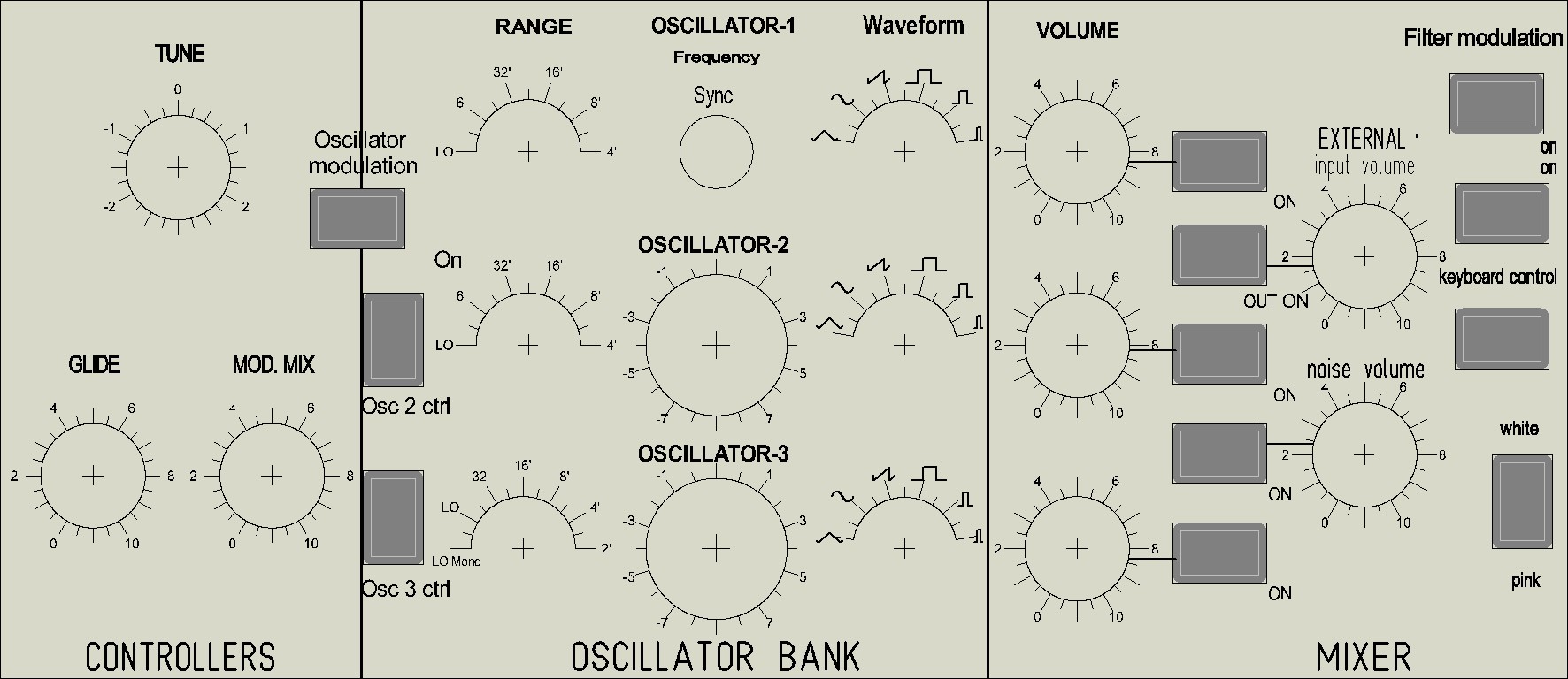
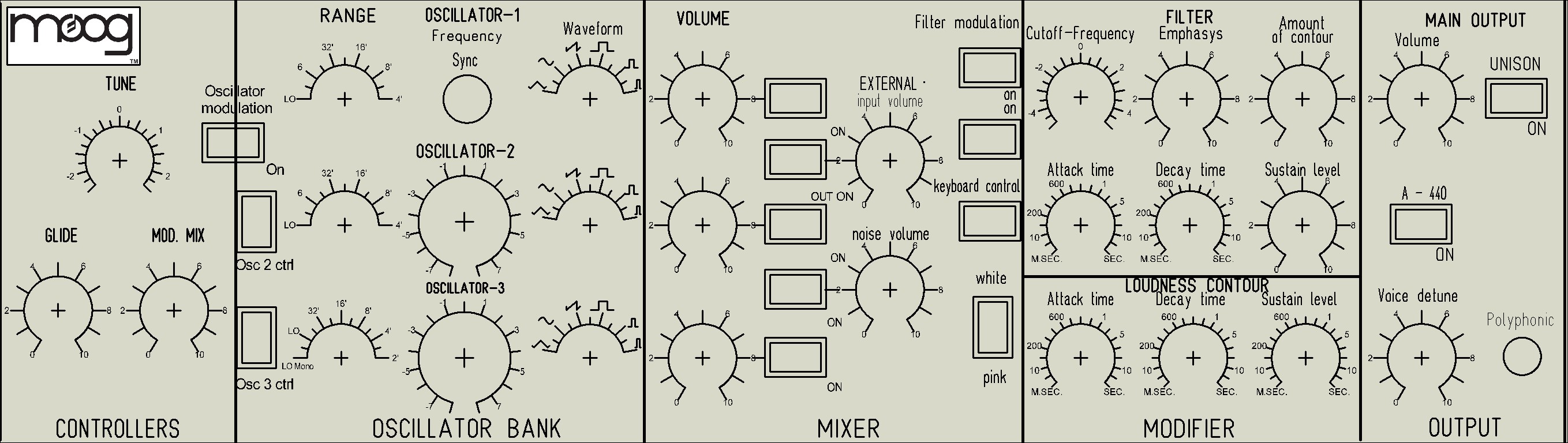
There are things to better align but with the new smaller switches the dimensions are now acceptable … 460 x 65mm Frontale MiniMoog.FPL (940.5 KB) Frontale MiniMoog2.FPL (119.8 KB)
Beautiful … thanks.
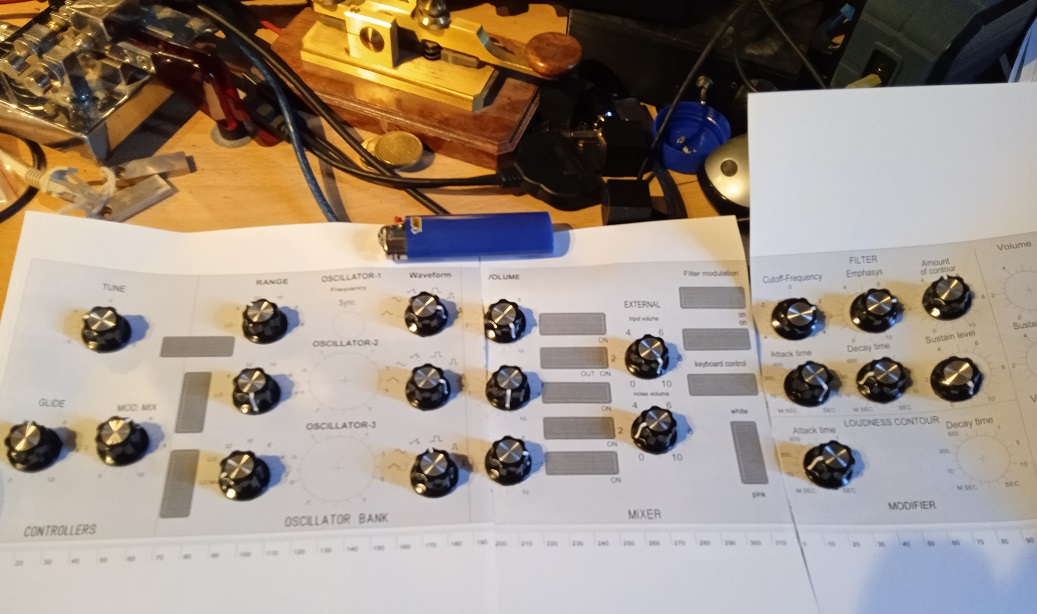
for now he will put some more “modern” switches to test everything … If the result is good then he will order them. A friend who uses the laser will engrave me a plywood board … but first I will do some assembly tests with a printed sheet of paper. If everything works (by the way, the controller also works with Arturia’s MiniMoog), then I proceed … Thanks
P.S.
in the previous photo there is an extra potentiometer in the MAIN OUTPUT window … I have already solved it