Now that is a decent excuse.
Italy- Greater China … 3-1 (Yesssssssss!!!)
Riban had done this:
pinMode(x1, INPUT_PULLUP);
pinMode(x2, INPUT_PULLUP);
pinMode(x3, INPUT_PULLUP);
The led is on digital pin 3 directly on the Arduino together with various switches.
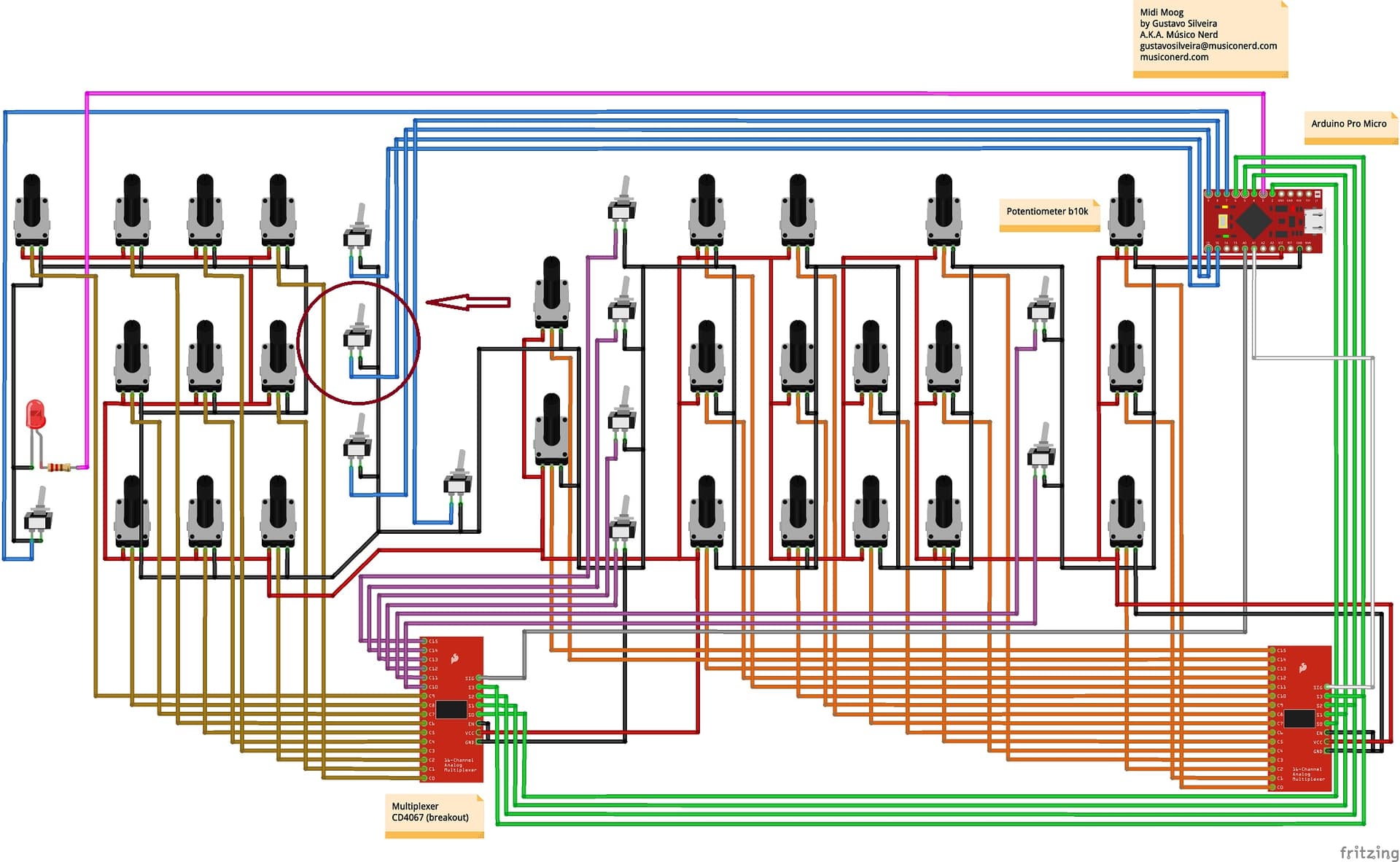
I am attaching the wiring diagram where the Multiplexer 3 is missing, to which 9 switches and 2 potentiometers are connected.

And the other three switches around it all work…?
Yes…
Have you tried swapping the wires for the non-working switch with a working one, swap them at the arduino end.
I also tried to move the wire from the Arduino to a multiplexer, to change the Arduino pin, to replace the switch … In my opinion the problem is on the sketch … on the CC numbers … which I tried to change. … but I insist …
I simplified the code, removing a lot of conditional preprocessor stuff so that I could see what was happening and cannot see why the code would caues the button to fail. There are some errors that should be corrected but none that should impact this issue:
- Not setting initial velocity (other than first param). This doesn’t actually cause an issue but ideally so should initialise, e.g.
for (int i = 0; i < N_BUTTONS; ++i)
        velocity[i] = 127;
But this isn’t required and I would be tempted to just initiate the array to all zeros, e.g. byte velocity[N_BUTTONS] = {};
-
Using wrong constant to create BUTTON_ARDUINO_PIN. The array is created too long. This isn’t an issue but could be if other parts of code change. The array can be automatically sized thus:
const int BUTTON_ARDUINO_PIN[] = {7, 8, 9, 10, 16}; -
Overlap of switches and pots on mux. Pin 10 appears to have been assigned to both digital and analogue multiplexes. In fact it is not used due to the size of array being correctly defined as 10 but for clarity the following change should be made:
{0, 1, 2, 3, 4, 5, 6, 7, 8, 9, 10}, // pins of the first mux
changed to:
{0, 1, 2, 3, 4, 5, 6, 7, 8, 9}, // pins of the first mux
As I understand it, your problem is:
Symptom: Toggling a switch does not trigger a CC32 MIDI message. Expected behaviour is for this switch to send CC32=0 when switch is opened and CC32=127 when switch is closed.
The non-working switch is connected between Gnd and PB6/D10/A10 of an Arduino Pro Micro.
This pin is configured for direct reading within the sketch.
I do not see an reason why this pin cannot be used with its internal pull-up resistor. If you have swapped two pins, e.g. 9 & 10 and seen that pin 10 still does not respond then I would suggest simplifying the code to just check pin 10, i.e. load a test sketch that just reads pin 10 and indicates its state. This could be by setting the LED to its state or printing to Serial. Both are implemented in this test sketch:
int last_state = -1;

void setup() {
    Serial.begin(115200);
    pinMode(10, INPUT_PULLUP);
    pinMode(3, OUTPUT);
}

void loop() {
    int state = digitalRead(10);
    if (state != last_state) {
        digitalWrite(3, state); // Show state of pin 10 on LED attached to pin 3
        Serial.printf("Input 10: %s\n", state?"HIGH":"LOW"); // Log state on serial port
        last_state = state; // We only want to show changed state
    }
}
*I have not tested this but it looks simple enough to be about right!
I also attach the simplified sketch which has not been checked and may have been over-simplified.
MidiMood-simplified.ino (8.4 KB)
I’ll do some tests this afternoon and I’ll tell you how it works. In the meantime, thanks as always for your help.
Arduino IDE return me this errors:
Arduino:1.8.19 (Windows 10), Scheda:“Arduino Micro”
C:\Users\Lanfranco\Desktop\MidiMood-master\Code\MidiMood-simplified\MidiMood-simplified.ino: In function ‘void setup()’:
MidiMood-simplified:103:5: error: ‘threadPotentiometers’ was not declared in this scope
-
threadPotentiometers.setInterval(10); // every how many millisiconds* -
^~~~~~~~~~~~~~~~~~~~*
C:\Users\Lanfranco\Desktop\MidiMood-master\Code\MidiMood-simplified\MidiMood-simplified.ino:103:5: note: suggested alternative: ‘potentiometers’
-
threadPotentiometers.setInterval(10); // every how many millisiconds* -
^~~~~~~~~~~~~~~~~~~~* -
potentiometers*
MidiMood-simplified:105:5: error: ‘cpu’ was not declared in this scope
- cpu.add(&threadPotentiometers); // add every thread here*
- ^~~*
C:\Users\Lanfranco\Desktop\MidiMood-master\Code\MidiMood-simplified\MidiMood-simplified.ino: In function ‘void loop()’:
MidiMood-simplified:113:5: error: ‘cpu’ was not declared in this scope
-
cpu.run(); // for threads* - ^~~*
exit status 1
’threadPotentiometers’ was not declared in this scope
This is the .ino file fixed to have no conflict on CCs.
What you used is no longer what I entered on the Arduino Micro. but the fact remains that the led should light up when I turn on the polyphonic function and instead it always stays on. And finally the usual switch (which is now on pin 14), does not work properly.
MidiMood_Lanfra.ino (22.0 KB)
There is nothing in the sketch to do this. The LED is turned on during setup but is not subsequently modified in any way.
What function have you assigned to this switch and have you checked if it is sending the MIDI CC?
Riban, IT WORKS !!! I changed the CC number of the damn switch several times and in the end I found one that did not conflict … Now I fix the two LEDs and they are good.
I did not understand what was wrong but it works …
I noticed that there was no code to regulate the LED lighting … but since another one would be needed on the Frequency sync switch, I will put two two-way switches and in one way I will bring the 5V for the LEDs … …
Now, if you could find a way to put Arturia MiniMoog in the Zynthian (or something similar, but VERY similar) it would make this old man’s dream come true.
While I am waiting for the front from China … if I wanted to put the switches in the place of the potentiometers in the six points where they would go … to make them work I would have to measure the resistances from the potentiometers in the moments in which they move the virtual switches on the PC and recreate the same resistances on the switches? Or can you make it work with incremental values on the sketch?
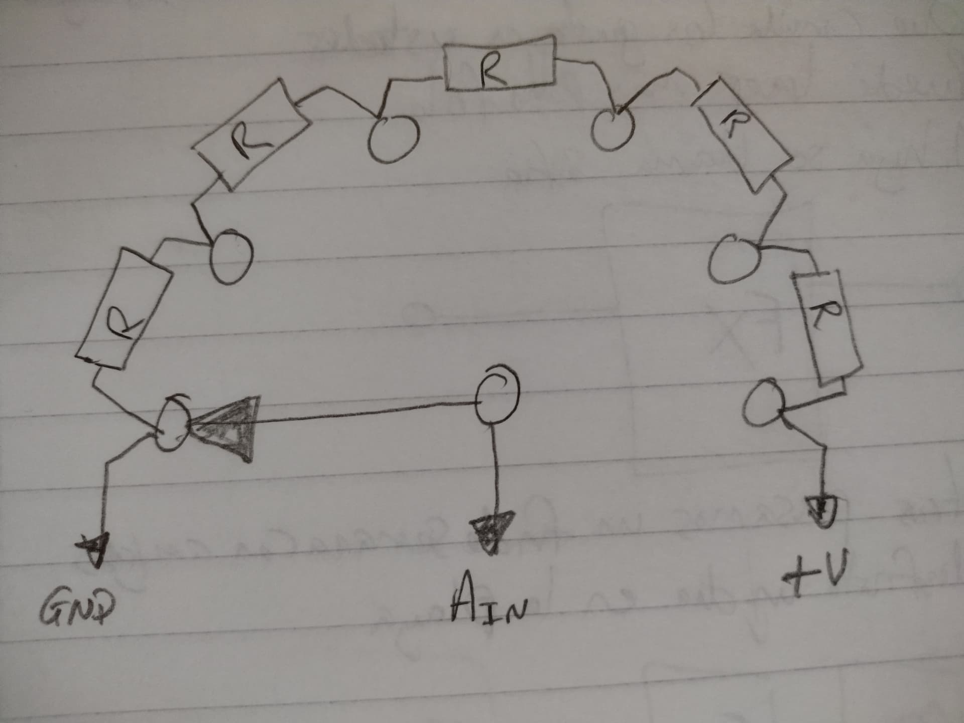
I didn’t completely understand what you are asking but I think you are planning to use multi-position switches and read them as analogue values. This can be done by connecting equal value resistors between each adjacent switch point, connecting ground to one end, +V to the other end and taking the switch common to the ADC. The resistor values should add up to similar to your existing pots, e.g. if your pots are 10k and you have 6 switch positions (5 resistors) then each resistor would be 2k. This can be approximate.
You need to denounce by ensuring analogRead() gives the same value for a period, e.g. 50ms. You also need to add hysteresis or range limiting, i.e. a range of analogeRead() values are interpreted as the same value.
Thanks Riban, I’ll study it
Sorry! I was over thinking it a bit yesterday… Here is the circuit:
This goes to one of your analogue inputs, e.g. a mux input. Then the software is probably looking for a single CC to indicate the switch selection, e.g.
| Switch position | MIDI CC Value |
|---|---|
| 1 | 0 |
| 2 | 25 |
| 3 | 51 |
| 4 | 76 |
| 5 | 102 |
| 6 | 127 |
In which case this should just work. The switch and resistors act just like a potentiometer but with discrete steps. So it could be quite simple. If the software requires different CC for each switch position then you need to consider what I said above, but I reckon that is unlikely. For example the waveform selection is likely to be a single CC.
1 Like
Thanks Riban, all very clear.
I posted a video on YouTube to show you the prototype in operation.

12 Likes
Very good job!!!
Fabrizio (IW1AWF)
1 Like
Grazie da IZ3ZLU
1 Like