The prototype is starting to be born …
7 Likes
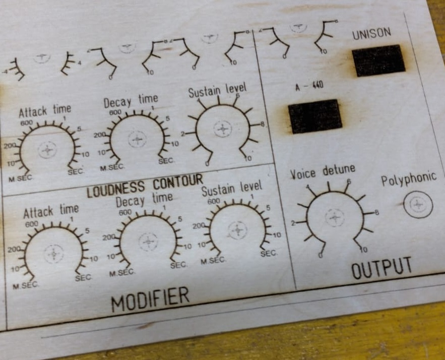
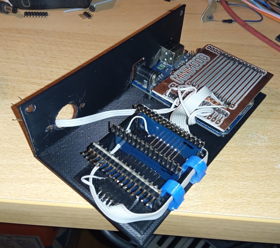
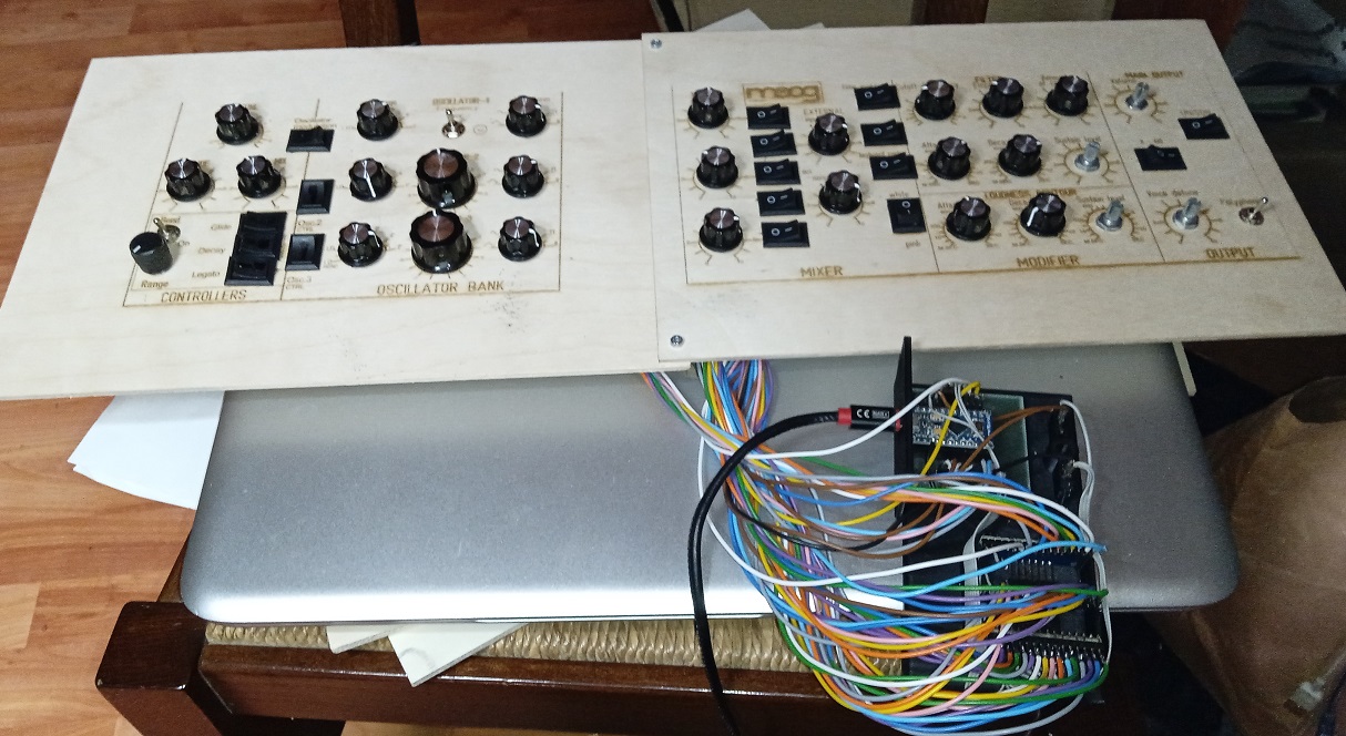
I assembled the prototype of the controller electronics … Riban will be scandalized by the homemade pcb with the cnc instead of the photoengraving  … but it works perfectly.
The support is printed in ABS with a 3D printer but I am improving and strengthening it. Since I want to control the Zynthian but also Arturia’s MiniMoog, I had to use three multiplexers to have enough ports for all the controls.
If anyone wanted to build this madness … soon I will put the files on my site iz3zlu.weebly.com … obviously opensource.
4 Likes
I am very happy to see pragmatism winning out. Progress is good - although maybe not at any cost! Keep it up and we hope to see more of it soon.
1 Like
Thank you Riban
If by “at all costs” you mean money costs, I have another 3 (original)Arduino Uno in the drawer, potentiometers and buttons I have to sell … the only expense were the three multiplexers (4 euros).
I assembled and loaded the firmware, but I had to modify it because, having put all the MiniMoog controllers, two Multiplexers were not enough. I then changed the firmware to work with three Multiplexers, but I have a CC signal that repeats indefinitely.
Finally I used the MidiMood firmware because it transmits MIDI via usb …
Could someone familiar with Arduino check that I haven’t made any mistakes?
many thanks
MidiMood.ino (22.0 KB)
P.S.
I partially solved … now I have the problem that the Cutoff knob moves the Modulation even if I try to set it for the Cutoff
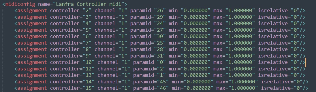
Opening the configuration file of the MiniMoog I see that the two values that I cannot set are missing and coincidentally they are the two pin 0 of the multiplexers … controller 1 and 11
I absolutely love this project and I can’t wait to see it up and running! I noticed the ino you’re using is from Gustavo Silveira of Nerd Musician in case anyone else is following this - his midi controller courses are wonderful! Want me to see if he has anything written on the course page about the minimoog script? Besides something in the code, maybe the way you have those pins connected to the arduino is messed up somehow? It’s suspicious because it’s the same pin for both mux chips so it almost smells like an error that got copied and pasted?
Thank you, but I solved it. I didn’t have to put the number 1 in the CC list because it is reserved for Weel modulation. Now everything works apart from the LED of the Polyphonic which is always on.
1 Like
So cool!! Can’t wait to see it all put together!
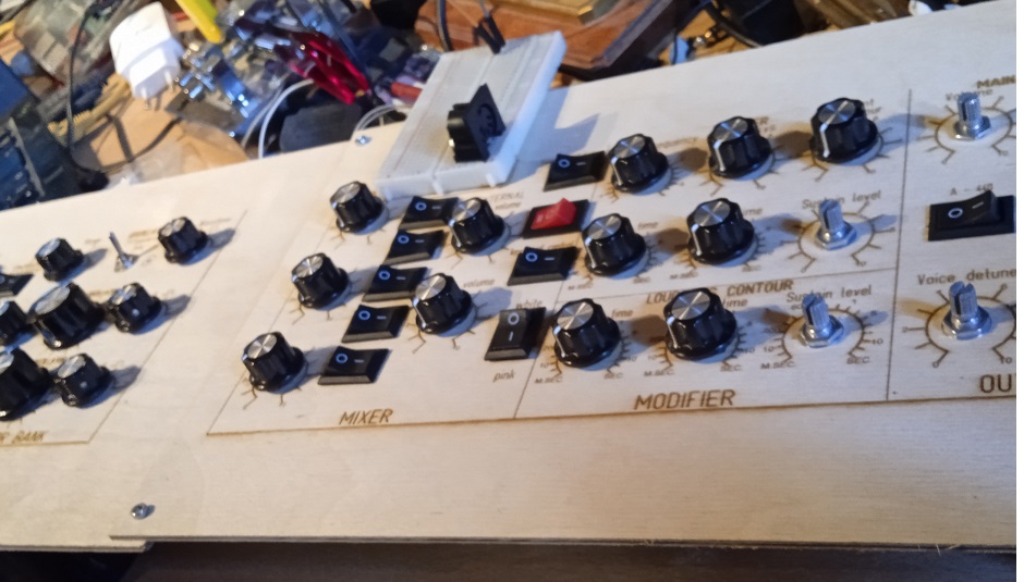
You are satisfied … The panel is provisional and I am waiting for it to be printed in China. Now everything works apart from the led and a switch that I can’t get to work.
You are not relying on an Interupt coming in on a pin that doesn’t support Interupts are you…? I lost about a month to that one once.
Apologies if this isn’t relevant…
You are always relevant … the problem is that you know too much, while I am a humble self-taught … I have attached the sketch above … it is not complicated. If you want to look at us …
1 Like
I demand this be chipped into stone . . .
2 Likes
You and Riban have written so many words to help me with the Zynthian … so on the stone you have to write “Relevant and kindly available to help” …
1 Like
Why thank you.
Now about your poly switch. Are you sure the hardware is all functioning.? You have swapped it with a working swtich somewhere else on the panel and proved that all works and the switch that previously works doesn’t affact the poly function? Simple stuff I know but often the reason, especially with rigs that are half way between prototypes and production…?
The led is connected to a pin of the Arduino and I tried to replace the pin … but in the sketch I see the pin setting but nothing that describes when it should work. The problem with the switch is that it crashes and seems to go on and off all the time by itself. Probably a conflict that I can’t find …
You are protected by the existence of other switches which respond properly so you are looking for edge case issues…
Remember that a brief short circuit will probably do that sort of thing, so a mechanical/electrical examination with that in mind is a good idea.
It’s really important that you place the issue in either hardware or software or the true peak of fault finding a combined software hardware problem.
I had no Internet today (changing ISP) so I had time to look at your script and made these observations:
- Velocity is only defined for first switch
byte velocity[N_BUTTONS] = {127};
This only initialises the first button’s velocity value to 127. All others will be initiated to 0. - x3 pull-up not enabled
pinMode(x1, INPUT_PULLUP);
pinMode(x2, INPUT_PULLUP);
These two lines enable pull-up resistors on the first two mux address lines but you are using a third so should add:
pinMode(x3, INPUT_PULLUP); - Reuse pin 3 for mux and led
The same pin (3) is used for both which may cause issues. - Reuse mux pins for analogue and digital
This was mentioned above by @dComposer. It may be working but it is likely to be inefficient and may have some odd edge-case effects. I would suggest redistributing the pins so that analogue multiplexing and digital multiplexing use different pins.
How are you multiplexing the digital pins (switches)? I would use a diode protected matrix which is cheap and relatively easy.
I am wary of having anything chiselled in stone that relates to @wyleu and me. It is likely to need many amendments before we both accept the wording and the chisel is likely to be blunt if @wyleu is allowed editorial control!
1 Like
As soon as the volleyball girls’ match (Forza Italia) ends, I make the changes. Thanks Riban