Encoders directly to the GPIO of the Pi 4?

Hi, sorry the delay but I was taking care of my son these days.

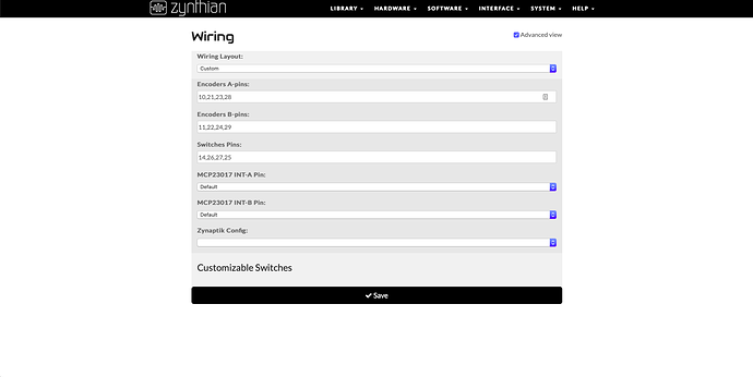
I wire the 4 encoders on the GPIO like on your schematic. The thing is with the web config, I tried cloning your photo configs but doesn’t works.
Tryed too putting the BCM numbers but doesn’t works too.
With your photo configs only works fine the switches. No one encoder can turn ok any parameter of any Zynthian layer.

I don’t get why the WPI and the BCM.
To be clear, I wire the pins physical on the GPIO numbers and then on the web config put the WPI numbers of all the wires. But all works like the switch Zynthian option of the encoder. If I push it works but if I turn the encoder makes the same thing like pushing it :S
I


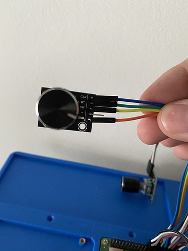
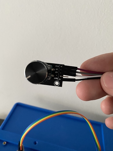
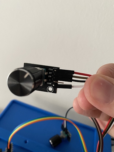
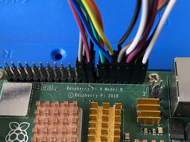
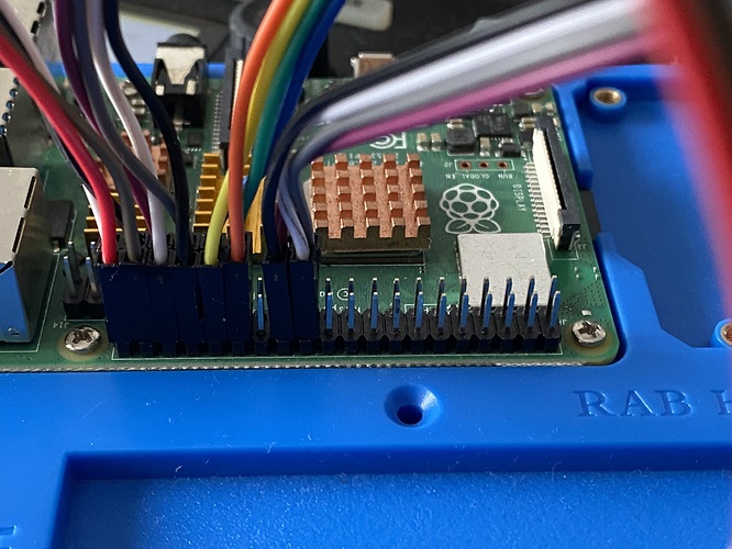
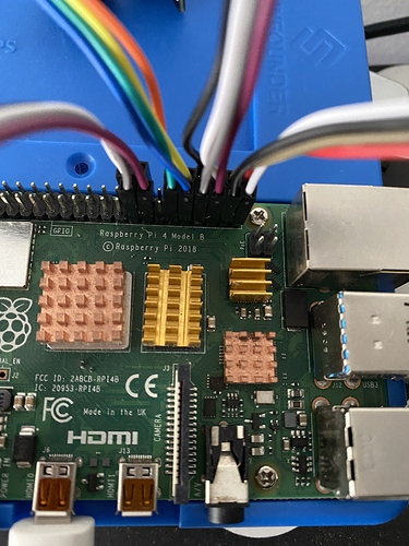
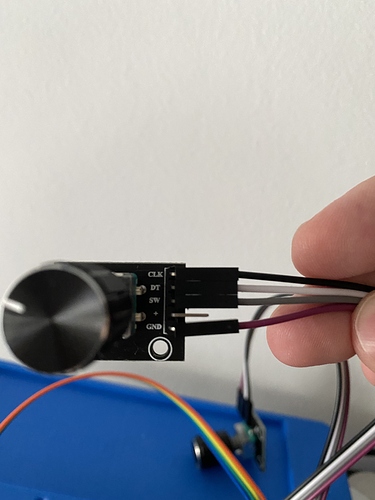
Here’re some pics. I think i wire it like @wyleu says on his photos.

The first encoder wired on physical pins 23 SW (click or switch), 24 DT (pin A), 25 GND and 26 CLK (pin B). This encoder only transmits “back” on the zynthian, the click and the encoder in booth ways.

The second encoder wired on physical pins 29 DT (pin A), 30 GND, 31 CLK (pin B) and 32 SW (click or switch). This encoder only transmits “layer” on the zynthian, the click and the encoder in booth ways.

The third encoder wired on physical pins 33 DT (pin A), 34 GND, 35 CLK (pin B) and 36 SW (click or switch). This encoder only transmits “learn/shot” on the zynthian, the click and the encoder in booth ways.

The fourth encoder wired on physical pins 37 SW (click or switch), 38 DT (pin A), 39 GND and 40 CLK (pin B) . This encoder only transmits “select” on the zynthian, the click and the encoder in booth ways.

I just don’t understand how is the comparation with the webconfig and the physical on the PI.

have you ssh access to the zynthian …?

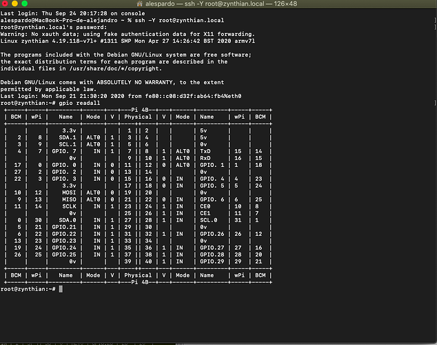
I can’t remember the name of the command line utility ( gpio readall… details in Encoder mapping for Direct I/O connection ) that will show you the actual status of the pins on the Pi…

ModMyPi MCP23017 pHAT is another thread with some encoder details. Are you sure the switches on the encoders are wired to zero? I’ve had some odd connections on them…?

Thanks for the pictures and detailed connection details. I can see the issues…

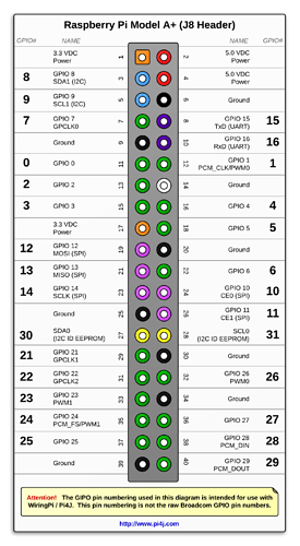
First you must use the WiringPi numbering scheme, not the BCM scheme so use these numbers:


Next you need to avoid the serial port on physical header pins 8 & 10 (GPIO 15 & 16) as these are used by Zynthain for its physical MIDI interface. Even if you don’t wire it out the Zynthian still enables the MIDI port and uses these pins.

I have tested each of the following GPIO and proven they all work so you should be able to wire to any of these for switches / encoders: 8, 9, 7, 2, 3, 12, 13, 14, 30, 21, 22, 23, 24, 25, 1, 4, 5, 6, 10, 11, 31, 26, 27, 28, 29.

If you intend to use I2C for anything (now or in the future) then avoid using GPIO 8 & 9. If you intend using I2S audio then avoid using GPIO 1, 24, 28 & 29. If you use GPIO 9 for a switch contact then you can use that switch to turn the Zynthian on from its standby state (off but power applied, e.g. after a manual power off). You may wish to avoid using GPIO 30 & 31 which are used by Raspberry Pi to access onboard EEPROM.

3 Likes

Here’s the shot of the ssh

What i read on the other thread is the people desolder the resistors of the encoder


jonathaslacerda

Dec '18

Finally I could to test the resistors removal from KY-040 and like @masterkey told previously, worked like a charm. Now I’ve three things to do: build the case, build an arduino based usb-midi controller and maybe upgrade the raspberry to latest version (3B+). The zynthian gorgona image most recent works with raspberry pi 3B+?

I change the web config with your numbers, now all the encoder switchs works like they need to do. But the encoders still making the same thing like the switches.!

1 Like

But the encoders still making the same thing like the switches.!

Watch gpio readall when pressing the encoders.

You should see activity on two GPIO input pins when you turn an encoder and one GPIO input respond when you press the encoder switch. Sometimes this can be hard to do without turning the encoder slightly.

1 Like

I don’t understand what you mean.

Have you rewired encoders to match your new webconf configuration?

Do all 4 push switches operate as expected?

What are each of the rotary encoders doing when you rotate in each direction?

1 Like

Yes the encoders make the same thing like the switches. On both ways.

zynthian gpio (17.2 KB)

I move the encoders or push the switch and run the comand but all stills the same.

I change the mistaken numbers on webconfig acording your photo. The wires i think are ok on the GPIO there’re pined right?

The switches working fine, the problem are the encoders. They act like the switches on both ways.

Could you do a small video showing what you mean?

Yes will do. How is the top weight of a file for update here?

First, I apologise for misinterpreting the photo of the Raspberry Pi header the wrong way round. I have drawn out a table that I think represents your wiring:

Use GPIO Rpi Header Encoder pin Colour
Encoder 1 A-pin 10 24 DT White
Encoder 1 B-pin 11 26 CLK Black
Encoder 1 Switch-pin 14 23 SW Slate
Encoder 1 Common Ground 25 GND Violet
Encoder 2 A-pin 21 29 DT Green
Encoder 2 B-pin 22 31 CK Blue
Encoder 2 Switch-pin 26 32 SW Yellow
Encoder 2 Common Ground 30 GND Orange
Encoder 3 A-pin 23 33 DT Slate
Encoder 3 B-pin 24 35 CK Violet
Encoder 3 Switch-pin 27 36 SW White
Encoder 3 Common Ground 34 GND Black
Encoder 4 A-pin 28 38 DT Slate
Encoder 4 B-pin 29 40 CLK Red
Encoder 4 Switch-pin 25 37 SW Black
Encoder 4 Common Ground 39 GND White

Please confirm this is correct. (I had to predict some because they were not visible within photos.)

The rotary encoder will close its two switches in a quadrature manner as you rotate it. In any rest position both switches will be open, i.e. there will be no contact between DT or CLK and GND. As you rotate from one detent to the next the switches change: First DT will close then CLK will close then DT will open then CLK will open as you return to the next detent rest position. Rotating in opposite direction will cause opposite behaviour. This means that to detect encoder rotation you must run the gpio command whilst holding the encoder partially between detents. I found this tricky to get reliable results . Also, the GPIO must be configured as input with pull-up which may not be the case if Zynthian is not running. (You could do this manually with some code.) I wouldn’t try to test encoder rotation with gpio command unless you are desperate! With the wiring in this table and the webconf from your last posted screenshot have you tried Zynthian and what is its behaviour? It should work assuming you are not using these pins for other purposes for example you should configure soundcard to USB or internal sound and display to HDMI.

2 Likes

Here’s the video

https://drive.google.com/file/d/1ms2Kz59yqzSuBXmbma5hESU1GmhMVAJN/view?usp=sharing

yes the pins are like you describe. I rewire all again on this order.
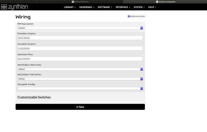
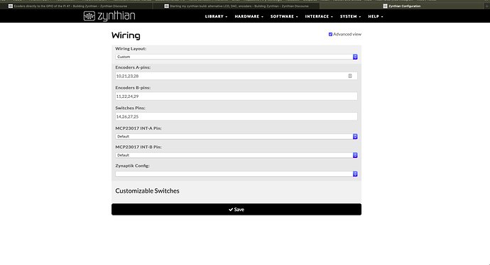
The webconfig is this:

And the wires like this:

See the video on the link:

https://drive.google.com/file/d/1ms2Kz59yqzSuBXmbma5hESU1GmhMVAJN/view?usp=sharing

And thanks to all for the patience and help.

1 Like

The reason you are seeing this behaviour is because the rotary encoder units have 10k resistors between each encoder switch / button and +. The Raspberry Pi has very weak pull-up resistors ~100k. There is an easier path to ground via the encoder pull-up resistors (2 x 10k resisitors). There are some solutions:

  • Remove the resistors from the encoder modules
  • Cut the tracks near each resistor
  • Connect 3.3V to the + pin of the encoder module

The last option is probably the simplest. You can daisy-chain or star wire from a single 3.3V pin on the Raspberry Pi. You should not use 5V as Raspberry Pi GPIO are not 5V tolerant.

1 Like

Assuming I don’t have an iron :sweat_smile: what’s the best solution? Buy one? :joy:

Thanks for your help all.

Initially just connect 3.3V to the + pin of each encoder to test if that works. There are two 3.3V pins on the Raspberry Pi header so you can test two encoders at a time. If that works then we can consider how to feed all four… :slightly_smiling_face: e.g. this would allow connection without soldering.

1 Like

Yes!!! They work but in wrong way. Need to change webconfig pins B to A. But now works. Maybe this wires work? https://www.amazon.es/gp/product/B07WK696RN/ref=ox_sc_act_title_1?smid=A2ZY4SNMU91J2Q&psc=1

That isn’t really ideal. It has 3 pins on each connector which is likely to not fit as expected on the header. Also it works out rather expensive. You could buy a cheap soldering iron, some stripboard and header pins and enjoy the fun of soldering something!!!

3 Likes