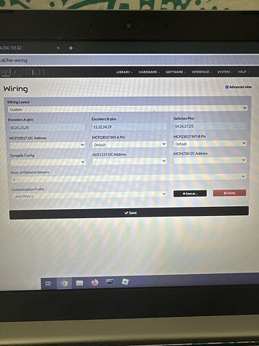
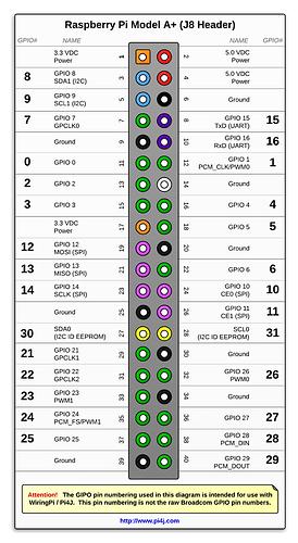
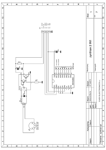
Encoder mapping for Direct I/O connection

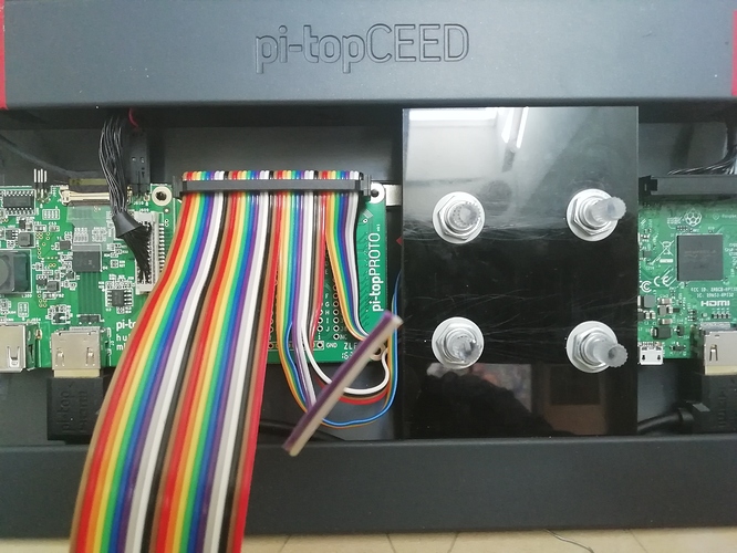
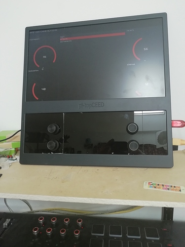
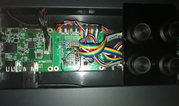
I’ve been putting some encoders on zynthian-ceed.local

Which, of course, involves encoders of various sorts…

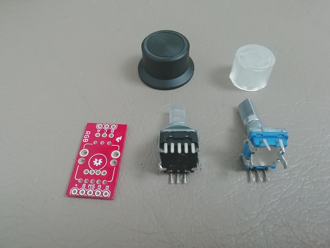
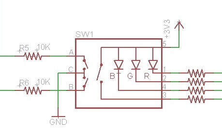
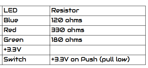
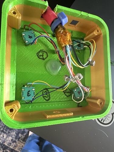
Now in this case I’ve used the red circuit board and the RGB encoder. . .

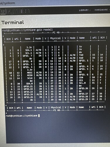
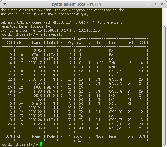
gpio readall is a command line utility that will help you lots…
(The following is a machine using my old style wiring…)

image

Initially I’m just getting the left & right encoder functions working . . .

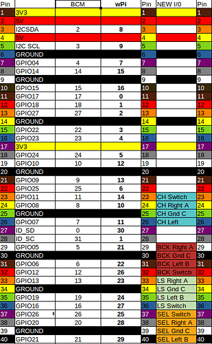
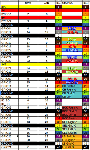
Which brings us to the new complete mapping chart for putting values in the Wiring Dialog…

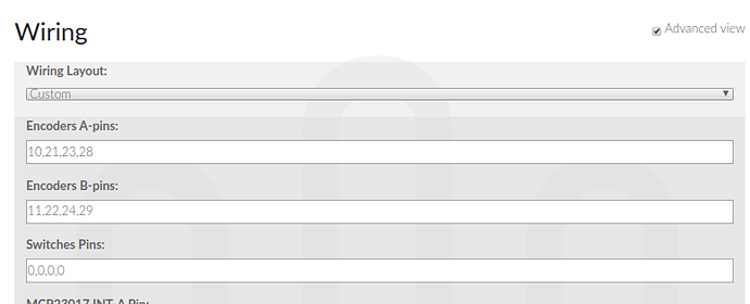
Take the values from the wPi column . . . .

image

And we have encoders that work !!

1 Like

Why don’t you wire the switch? Don’t they offer that.

It’s complicated. The Switch is wired between the pin marked Plus which is commoned to the LED’s
So the polarity of the pin is reversed.

Presumably I can code my way out of it, but I end up with a non standard rig. Similarly I could flip all the pins including the encoder to be pull low but again this isn’t easily configurable in an environment that does as many refreshes, reboots and rebuilds as I do. I am wondering about using 4 transistors to invert the pins, unless of course anyone can think of another solution.

rgb_encoder_pinout_better
image

Obviously I’d like to use the remaining 12 I/O lines as PWM LED controllers but sadly this precludes using GPIO04 (pin7) for the Interrupt for the i2C bus . . .

I’m just pleased I’ve managed to produce a chart of what values should go in the Wiring text fields… :smiley:

And you implemented the Switch as CUIA Action?

Hmmmm that’s an interesting thought, but don’t the MCP23008 pins still connect to OV for on?

I spent a fair bit of time getting the encoders into as close to the right place as I could. I have one remaining sheet of perspex and I think I will make the next one with the cuts down the centre of the encoder holes I might well reorder the panels as smoked rather than black perspex. That way I can see the LED’s inside the device…
Putting this together has been . . . . Involved. And taking it apart is similarly complex…

I’ve ordered a hifberry white case for a Pi4 & an ADC/DAC card for it so I can use this beast to control the Pi4 over Ethernet.

Anyone done a PD screen for lyrics?

Add a feature request. I am sure that @jofemodo and @mheidt can’t wait to add an extra option to invert each GPIO :wink:.

I have absolutely no doubt about their willingness in this regard … :slight_smile:

@jofemodo has certainly created a branch already and is mulling over the easter bugs he is going to hide for us.

1 Like

Well I now have some LED’s driven by PWM. (and am fast running out of colour combinations in Librecalc…)

from RPi import GPIO as gpio

ENCODER_LEDS = {
‘LS’: {‘red’: 12, ‘green’: 10, ‘blue’:7},
‘SELECT’: {‘red’: 21, ‘green’: 18, ‘blue’:15},
‘BACK’: {‘red’: 16, ‘green’: 19, ‘blue’: 22},
‘CHANNEL’: {‘red’: 8, ‘green’: 11, ‘blue’: 13},
}

for each pin in the above …

pin = gpio.PWM(pin, frequency) sets up a pin
pin.start(100) # sets up the led and sets the start state to off
pin.ChangeDutyCycle(value) # sets brightness value= 0 full on, value = 100 fully off

and after . . .

pin.stop()
gpio.clearup()

is the basis of this in Python.

Encoders certainlt react but I’m not sure it’s all correct . . .

But of course the I/O is all handled by lower level calls and it quickly gets overridden once the programme stops or is interrupted and does not behave nicely if the clearup isn’t run such that it sometimes wont run again on a restart.

So a clean start on a zynth . . . .
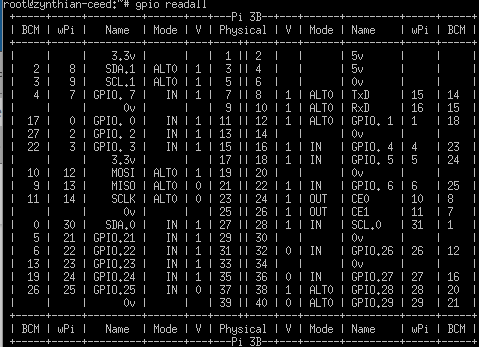
image

Whilst running python prog . . .
image

and after it’s finished . . .
image

pin 21 ( GPIO9 SPIO_MISO) runs High (Select Red in my world)
from start up and after the prog runs . …
2 Likes

@MrBroccoli has someone who cuts acrylic !!! WHo is …

Do you have an example of something they have cut and the cost?

Right I’ve finally got the transistor inverter working on four encoders.

I will remember to turn the switch on in webconf the next time . . … :smiley:

And now I have it working properly !!

Transistors BC549 with 2k2 resistor into the base, collector to 0V and collector to GPIO port, relying on pull up resistors.

A picture to convince you that 12C is the way forward and thats before you look at the back of the board. . . .

1 Like

If you are following this firstly I’m glad to see the chart on this thread. I couldn’t find it in the discv,

and secondly look at this thread if SPI pins like SPI block GPIO 7,8,9,10,11 is involved…

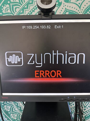
Hello :v:t2:, I am having issues with wiring the encoders. I have them wired the same way as listed above, but when I change the wiring from anything other “dummies” I get this error

I am using my these encoders

Does anyone have any advice on what I may be doing wrong ?

What I have been trying to use, but no luck

HI @LazerShow,
In my Zynthian Minimal (therefore without other things but a small sound card) I made these connections, but I’m using a display that doesn’t occupy GPIO pins. What display are you using?

Follow this numbering:


Numbers in bold are the ones to enter in WebConf

The Zynthian genes will advise you better… but I built a GPIO expander at least for the 4 buttons, which made my life easier…

Thank you :pray:

This has all come back to life around the Bugera Pedal. . . .