How do you find the Pi400?
Where are you going to mount the encoders?
How do you find the Pi400?
Where are you going to mount the encoders?
I have tried to trace your wiring from the picture. I only checked the first encoder you have labelled “CH” with the blue sleeve. It appears this is connected:
| RPi Pin | RPI Use | Colour | Encoder Pin |
|---|---|---|---|
| 6 | GND | Blue | SW |
| 8 | GPIO 14 / Tx D0 | Slate | DT |
| 10 | GPIO 15 / Rx D0 | Black | GND |
| 12 | GPIO 18 | Red | CLK |
This looks wrong:
Hi @riban!
Thank you very much, but I cannot understand your reasoning.
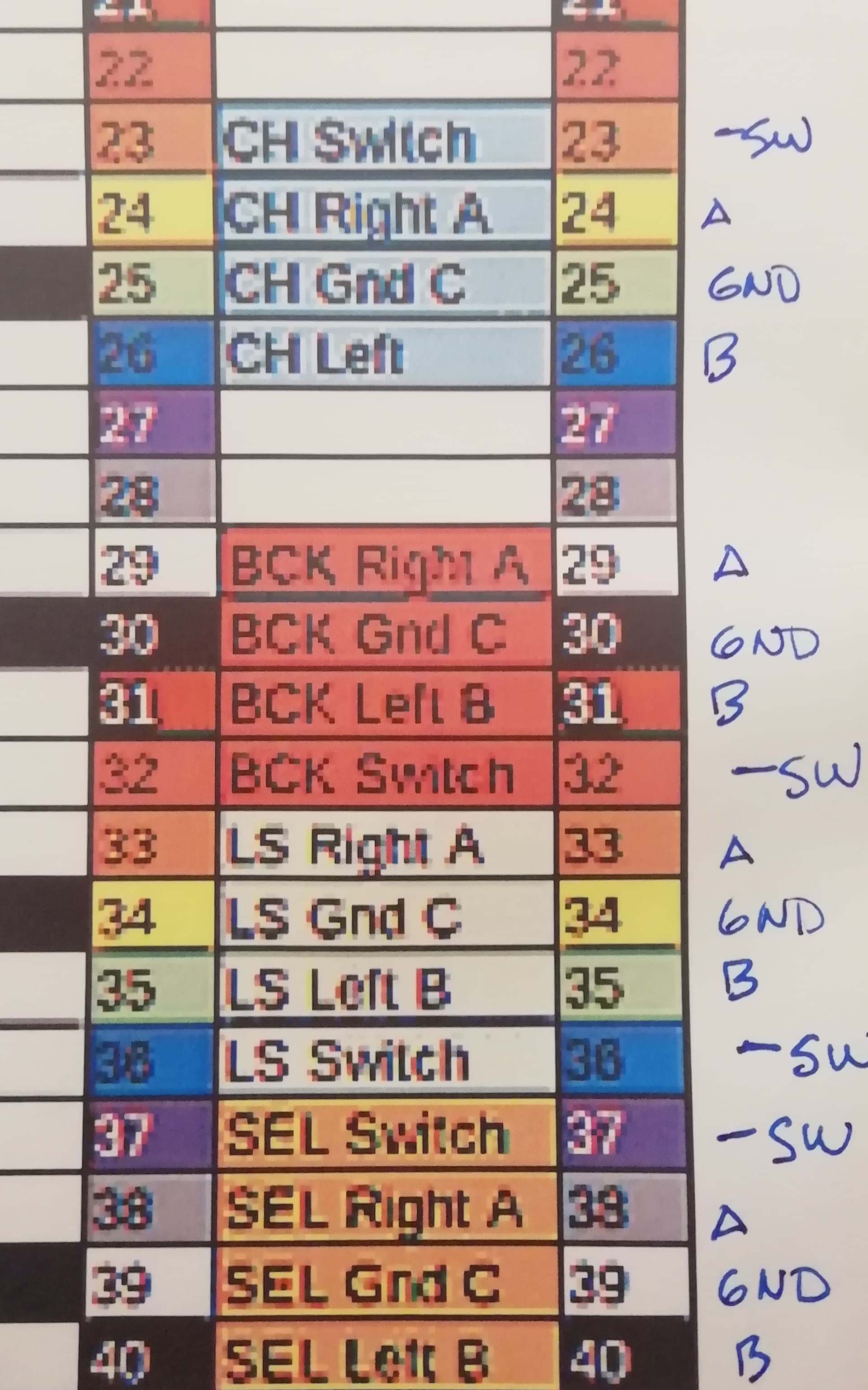
I used the next table as indicated upon
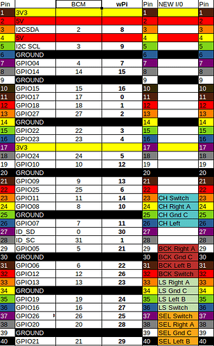
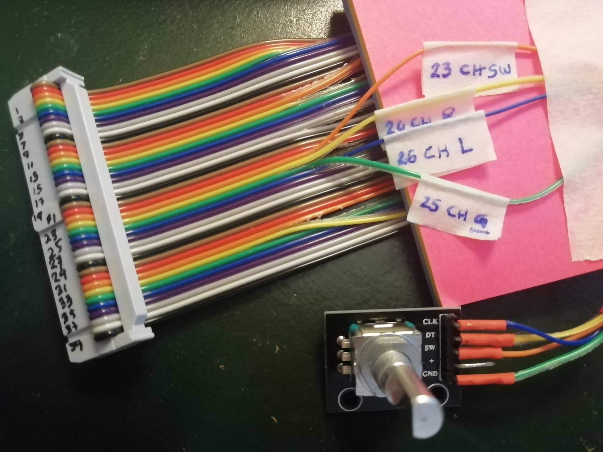
Based on the table nomenclature, I did this wiring over CH encoder:
| Pin | NEW I/O | ENCODER | Colour |
|---|---|---|---|
| 23 | CH Switch | SW | Purple |
| 24 | CH Right A | DT | Gray |
| 25 | CH Gnd C | GND | Black |
| 26 | CH Left | CLK | Red |
Is not correct?
What @riban tells you is that you wired the CH encoder like this
Which, as he stated is not the way… For example your black wire is not GND, but Pin 10, which is RxD
Ha! They won’t align with any of the UI which can be configured to place it’s controls on both sides of the screen or just one side.
Hi @Keeze101!
I appreciate your explanation but I still don’t understand. Please take a look at this:
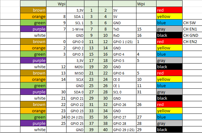
This was my guide to wiring all.
I identified every pin on GPIO properly, so I cannot figure why are you indicating 8,10,11,12 gpio pins instead of 23,24,25,26 that are which I soldered.
Sorry but I do not see the relation. At the same time, I am pretty happy to have connected it wrong, so I have the possibility to make it work, but, please I need to SEE IT
Hi @riban!
Yes I supposed that. But, initially, it doesn´t matter for me have the pots in a row and the controls over 1 or 2 columns not aligned at all. I suppose that will not represent a big problem getting used to such correspondence.
Well, if finally is uncomfortable, I will change them.
Right? Left? I will delay my decision until the last minute! ![]()
Tomorrow I will record a video showing the pin correspondence
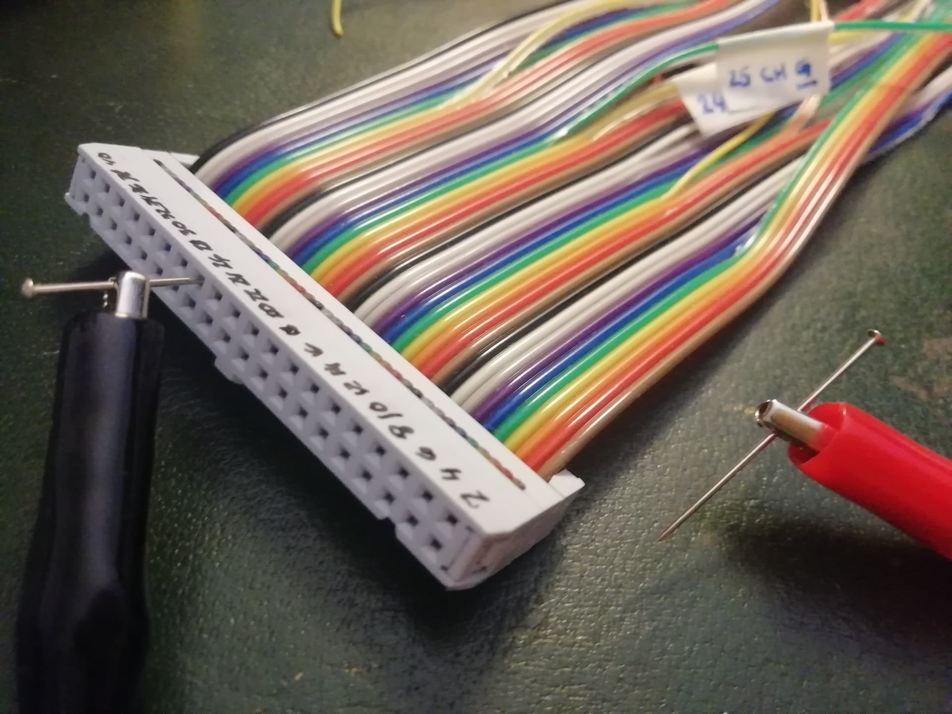
Looking to your foto of the connector, it seems that you numbered sequentialy on both sides. eg 1-20 on one side and 21 to 40 on the other side. But the connector is odd 1-39 on one side and even 2-40 on the other side… ?
Ouch! I din´t know that!
I guessed 1-20 and 21-40.
Moreover, reading the graphic I used, I could not figure out such thing.
Thank you very much.
In my whole life I had never did such assumption.
Big mistake. Big learning.
A long trail to discover about raspberry yet…
Start with the multimeter to identify the pins on the connector that are joined to ov. With the pi off buzz from exposed metal work to the pins and gnd or zero on the pins and match that up against the pin out of the gpio connector.
Then set the multimeter to voltage and after turning on the pi identify the 3.3v & 5v pins. Be careful not to short these out as you do so, that can damage the pi especially the 3.3v line.
Once you have done this you know which pins are which so you can check the ends of your ribbon cable to ensure these voltages are present at the end of your connector wires.
This will help you ensure which gpio pin is which.
And I colorcoated my drawing with the colors from the ribbon cable from @erasmo. So once confirmed pin 1 he can use my drawing to connect the encoders. @erasmo the drawing is excel, do you want it?
Many thanks. I will put in practice right now
Thank you very much. Yes, of course!
Please, observe the cutting-edge technology used to locate the raspi pins: sewing-pins ![]()
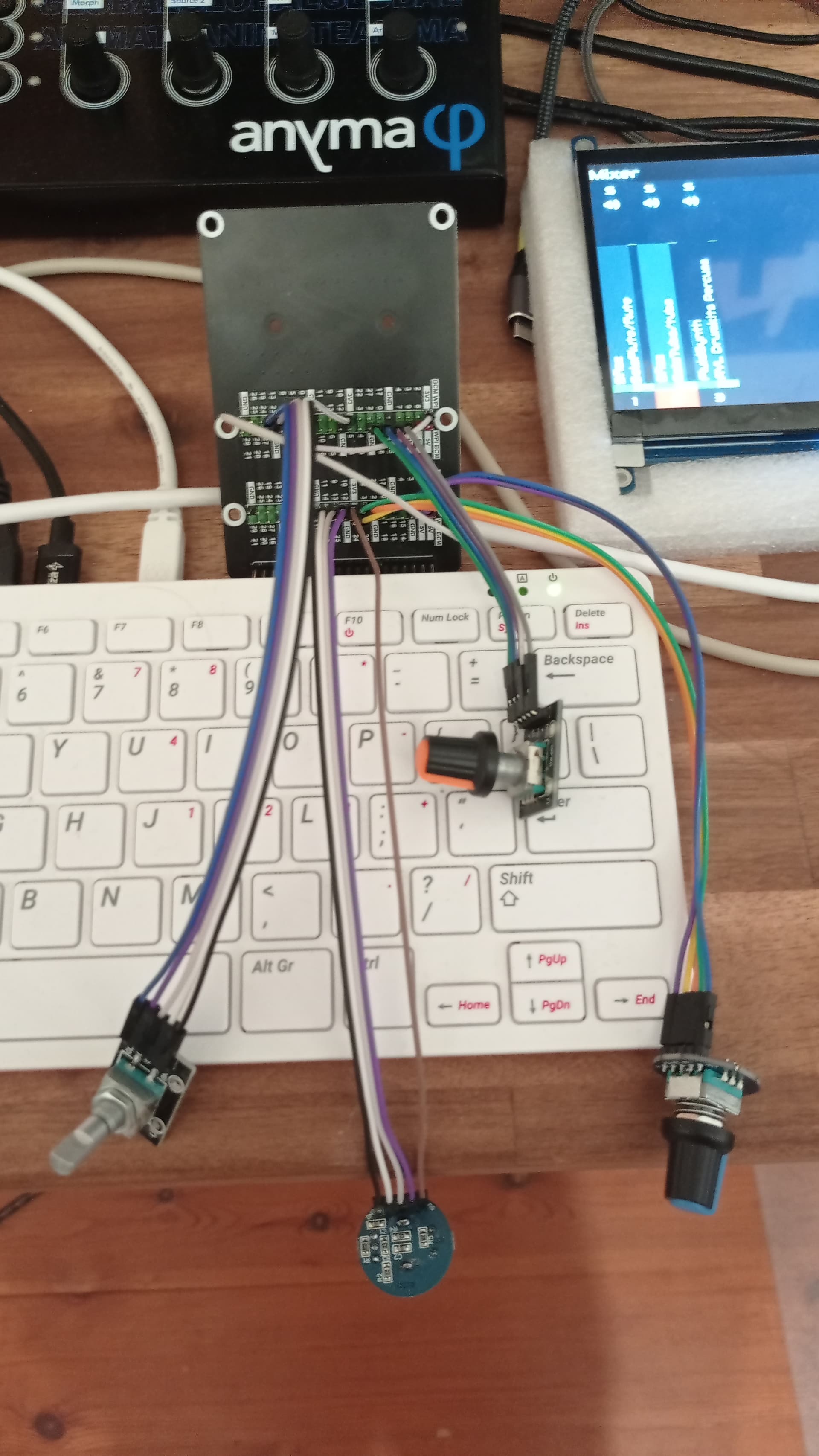
However, every time I am more confused. After testing the new configuration neither works: RED ERROR came to visit again.
Only first encoder soldered I must say
Can you measure volts from the bottom brown wire (pin1 = 3.3v) to the first White wire (pin 9 = gnd)
When you read 3.3v it confirms your pinlabeling
Oh, well, it seems finally I am making an advance. The DC reading shows 3,29v. with raspi connected to power supply. I suppose will be fine.
Now I attach next image to the manner of “spot the error”. Is not working
Maybe stupid question, do you have connection of + connector on encoder to 3.3V from GPIO?
I had experience with experimental wiring on RPI 400 when I used https://www.waveshare.com/pi400-gpio-adapter-c.htm , 4 rotary encoders a dupont wires. Up to 2hours of work and succesfull finished. The adapters have 2 GPIO pins so I have 4 pin of 3.3V source. On your cable have only 2 wires with power on 3.3V.
The pins are pulled high by the Pi, you don’t have to connect the + pin from these KY040 encoders