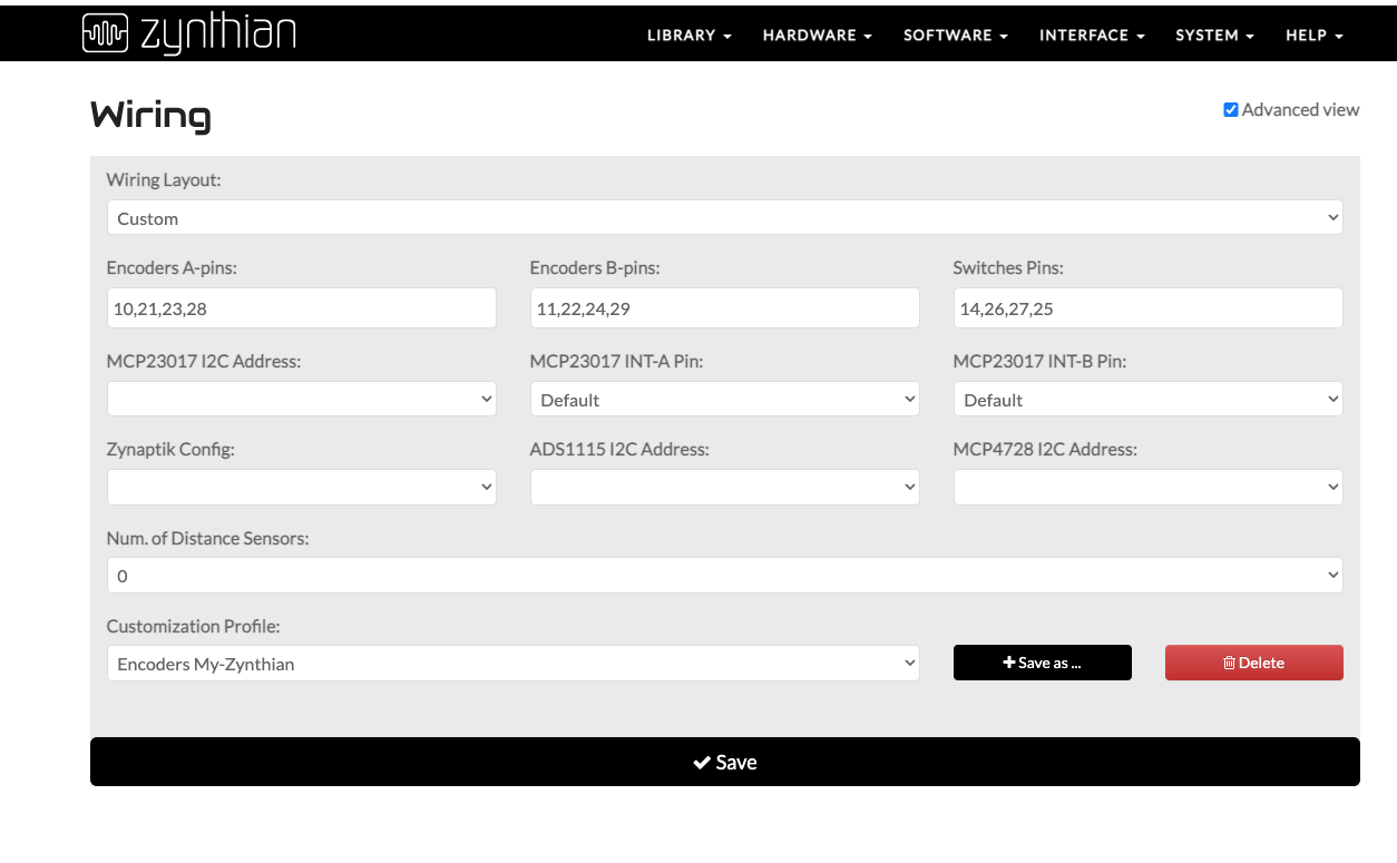
You have to use the WiringPi numbers (wPi on your picture):
A-pins: 10,21,23,28
B-pins: 11,22,24,29
Switches: 14,26,27,25
1 Like
Start with the select and back encoder switches and work up from there.
1 Like
Ok. I see. Was suspecting something was missing out…
Tomorrow will try again. I will comment later.
Thank you very much guys!
Hi @gilrain!
After changing settings as suggested, I am getting RED ERROR.
So, I ask again: may be a consequence of having soldered ONLY first encoder (CH) to test?
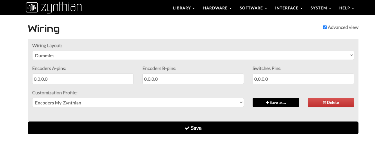
Does it work if you set hardware to dummies?
HI @riban!
I changed to dummies as the picture, and red error disappear but nothing works. Do I have to write the wiring of encoders on dummies and save?
I have a question. May be some kind of interaction with my sound card? I am using a Behringer UMC404hd in the sense that any of the pins was assigned to it?
One thing more. I have soldered all 4 encoders and problem is the same
Another more. I am using a PI 400. May be some kind of interaction with keyboard?
The reason I suggested setting to Dummies was to prove that it was the Wiring configuration that was causing the problem. With it set to Dummies can you see the UI and get audio out?
Putting a 0 in a specific place prevents that position working which is very useful for testing individual parameters.
Yes. Set to dummies the raspi worked alright again.
I did some changes copying other configurations I found from you. Specifically one, in which you suggested the A and B configs recommended, but setting all switches to 0.
Gave red error too.
May I have “burnt” an encoder with an improper hot application?
The first one I soldered with a more powerful iron, but last three changed to a soldering iron less powerful.
I doubt it, it’s all about 0v so you arent passing currents of any large size.
I found that guessing and trying does’t really help because the encoders require both pins to be connected for the software to make any sense out of it all.
The best approach I found was to use the switches to get it sorted out using the Back & select switches because these have the most useful effect…
Work out which pins these are on and follow the rather confusing route to work out which configs you need to put in the wiring sections.
Once you have the four switches worked out then proceed to the select encoder and connect hat up and select the correct values for your configuration.
That will prove one encoder ( the select) and once you have done that it’s just a matter of being methodical to sort out the others.
A parameter page is good because that does nothing other than use the encoders to move values on the screen rather than elements like menus, and it will allow you to see if you have the encoder pins the right way round.
Try to work out the relation between the GPIO pins & the pin from the chart.
Many thanks @wyleu!
I´ll try it.
Good luck. It’s just logical.
Do you have a multimeter and could you show pictures?,
Don’t worry how ‘creative’ the construction is, it’s all part of the process.
Do you intend to add the s1-s4 switches to your rig?
This zynth does good work most days…
1 Like
Hi @wyleu!
Thank you for your recommendations. I must try it.
As I am going deep in Zynthian project, my doubts, fears, and electronic limitations have started to vanishing after reading, and reading, and more reading, subjects about the topic; Raspi and arduino. Is a fascinating world in which, many dreams I ever had as piano player, come to life.
For today, I have this idea in mind : toast a fresh Zynthian OS in the card and try again.
Yesterday I experienced some difficulties when playing some minutes with my Zynthian “project”.
In a given moment, the sound started to play as if in stacatto mode. I believe that was a some kind of cc message interaction of my keyboard, after changing an instrument. That behaviour did not make any improvement after resetting and rebooting Zynthian several times.
Only got terminating the issue, after resetting my keyboard. From that moment, Zynthian started to perform well again. Strange.
Answering to your question: Yes. I have a multimeter. What kind of pictures/reading should I take to advance?
Probably it would be interesting adding switches but you know, encoders not working yet…, I see switches as an added difficulty ![]()
Also I had thought adding a general potentiometer volume ![]()
![]()
I will inform you of my advances.
Start with a picture of the device as it’s seen from the performers perspective. That way we can see what you have as your interface.
Then photgraph the back of the device, so we an see how the various controls presented to the performer, are connected to the Pi that’s doing stuff.
Then present individual details showing how individual components are implemented. Encoders edge connectors that sort of stuff.
It provides excellent context that descriptions often ignore.
Adding Switches: Put a little thought into it.
It costs nothing other than time.
Where would you place them on your hardware interface? What would you want them to do? how would you connect them to the Pi? Actually it’s a moot point because I dont think we actually support GPIO pin use of s1-s4 switches, they are only an option on i2c connected zynths( someone will confirm implement, or deny this…)
When the machine was staccato’ing did the red panic icon appear?
IT’s probably a good idea to read up the wikipedia page on rotary encoders, or incremental encoders as they should, probably, be more properly called.
First couple of paragraphs gives the idea. You can check they are working with a multimeter measuring continuity ( the friendly buzz mode…). Connect across the two pin, not the centre one and rotate the shaft, you willl hear a clicking of buzzes as you turn.
The great thing is this doesn’t just work at the encoder pins. It works all the way back on wires, so you can check it’s working, by disconnecting any connectors from the Pi & checking the connection makes it round that loop. It’s easier to do than describe…!
PAtience and understanding are the secret, and as soon as you get it right, you will forget it all as you just assume it works until something goes wrong, so make copious notes, so you don’t have to work it all out again, and take pictures they also can sve you many hours of head scratching.
1 Like
Hy @wyleu!
Here I start with some pictures of my setup (calling device to my cable mumble-jumble it should be a bit pretentious):
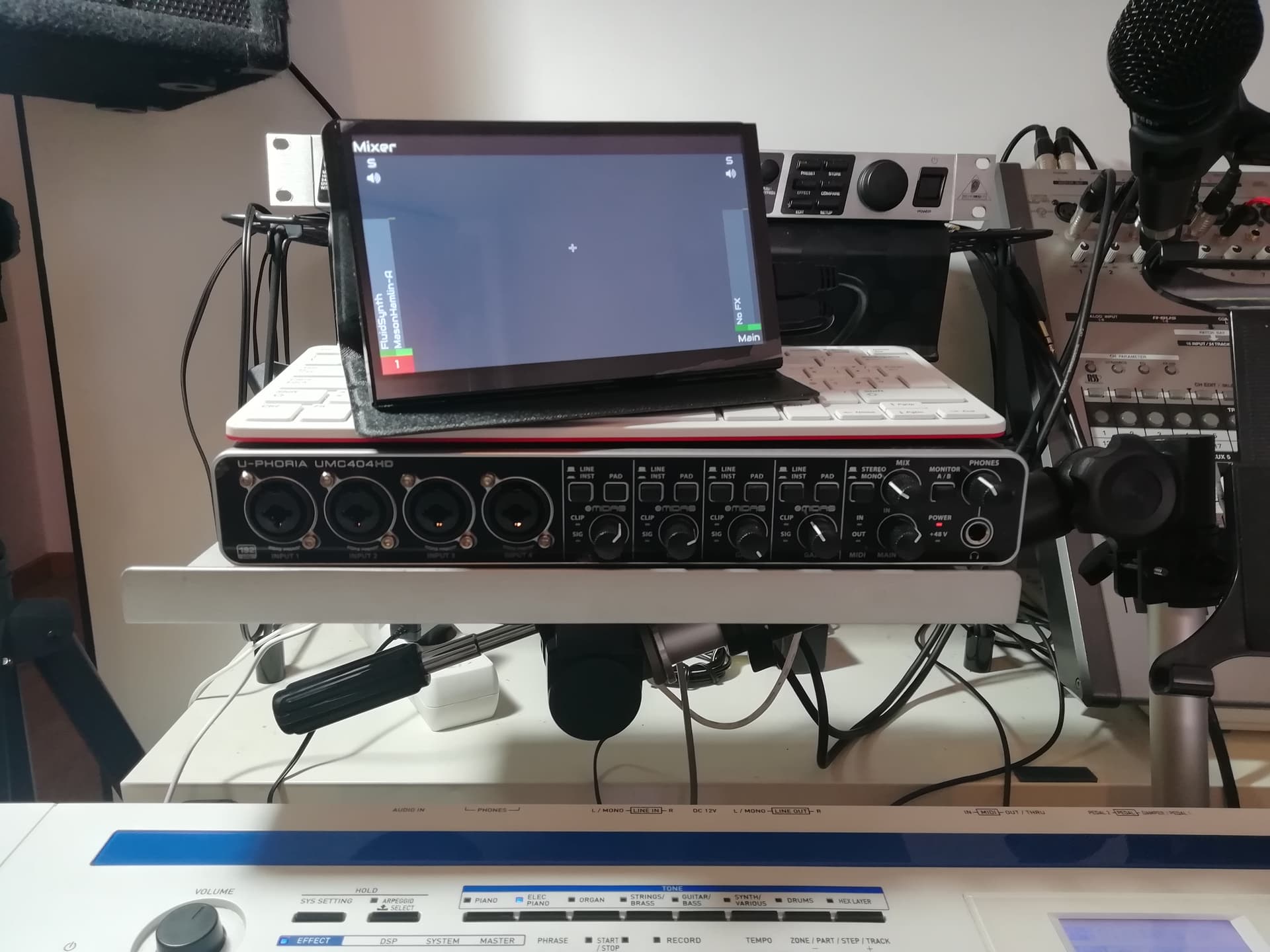
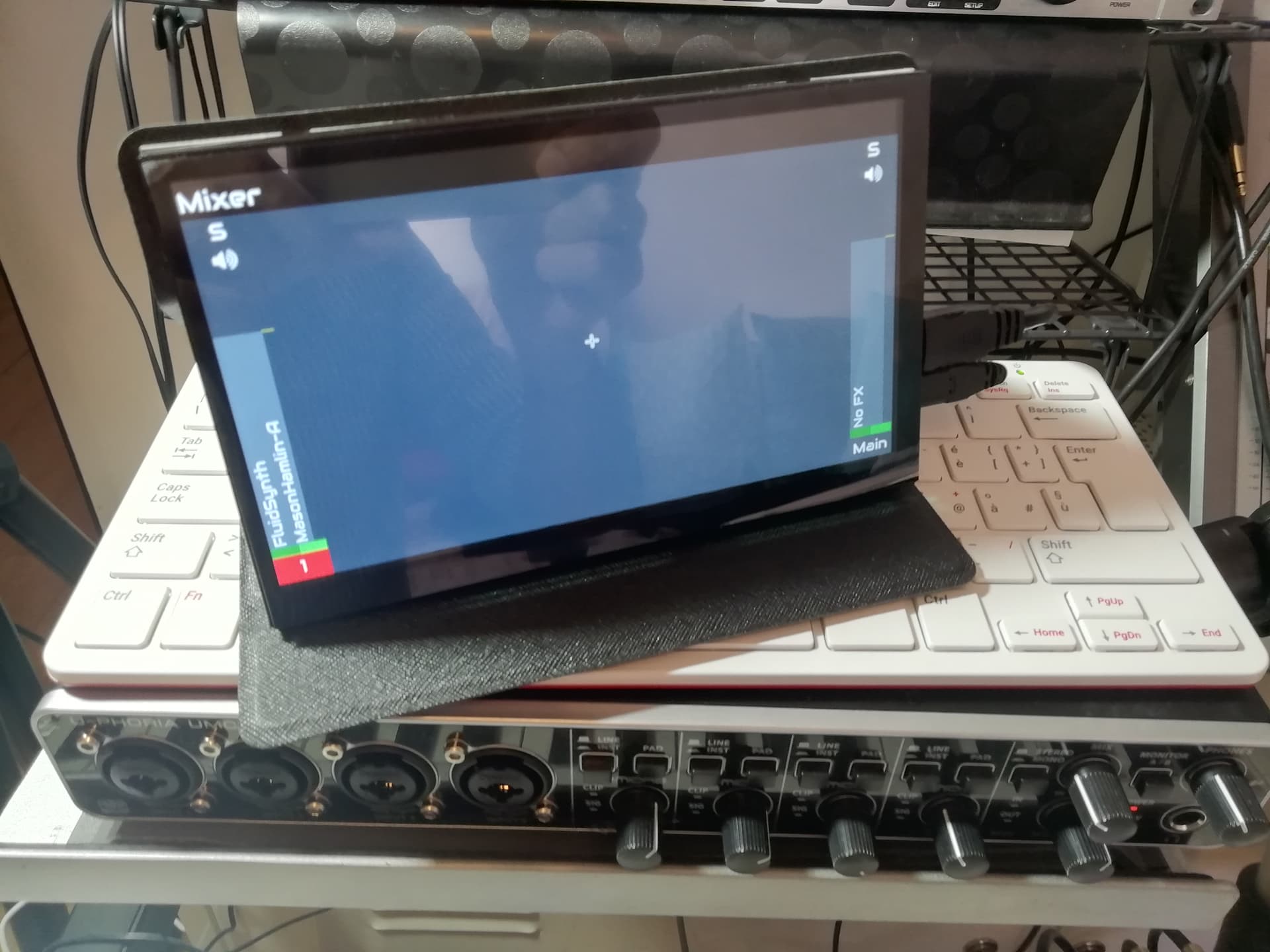
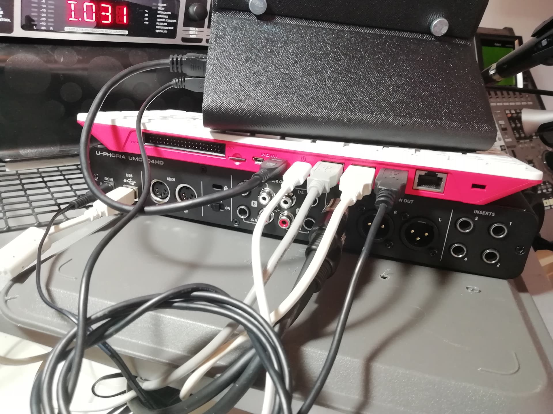
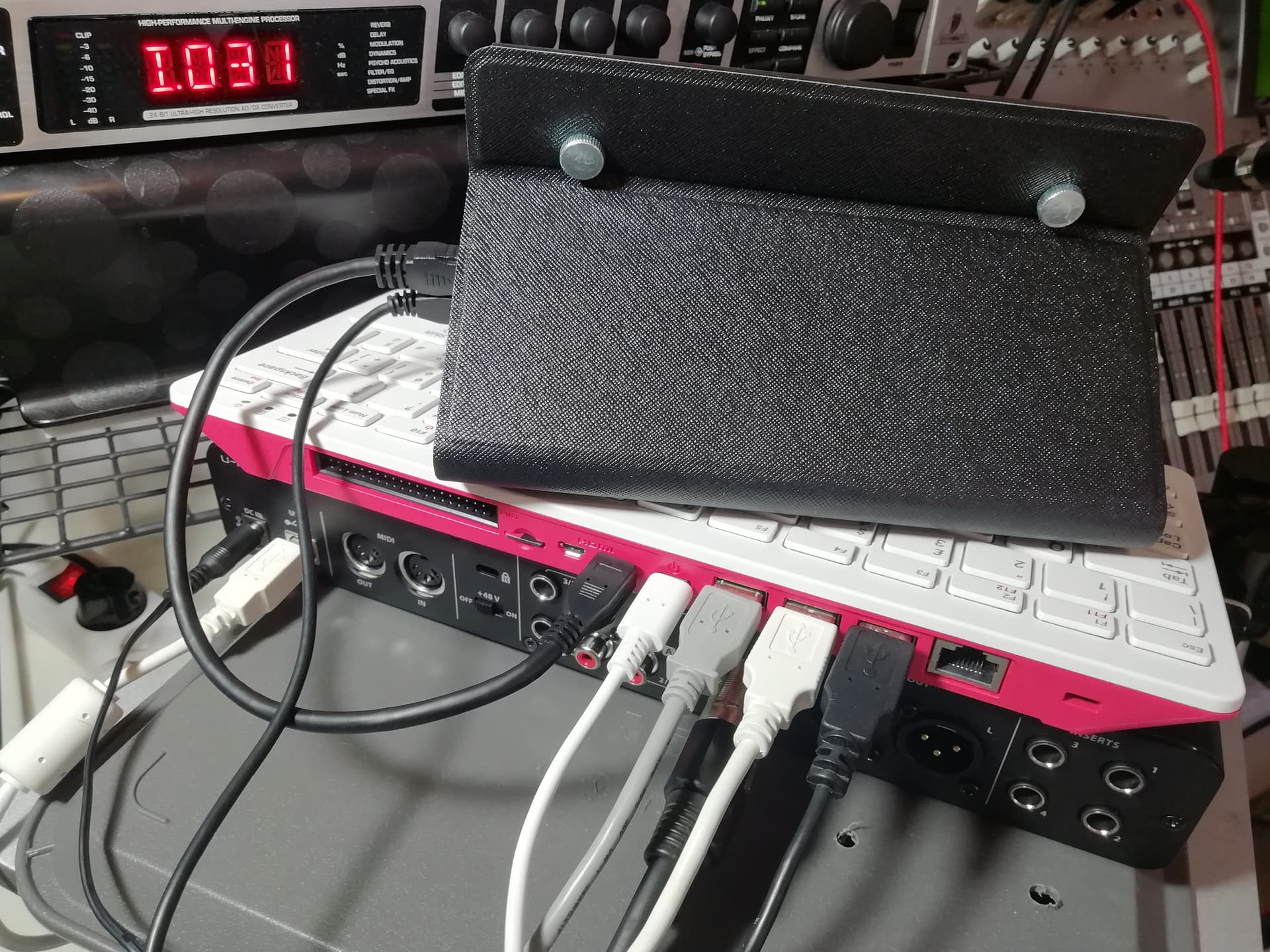
But, well, that so simple configuration, is working!
Now, I´ll show you my encoders direct gpio cable process:
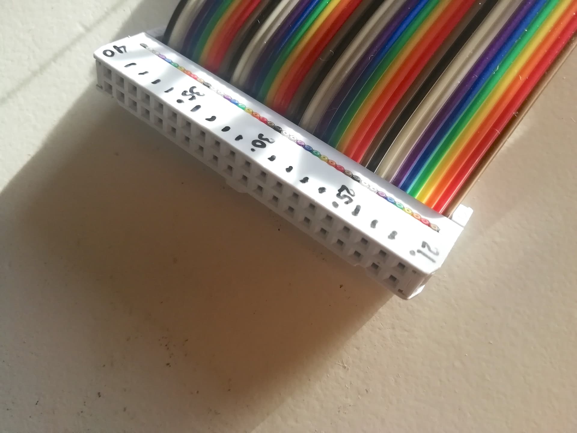
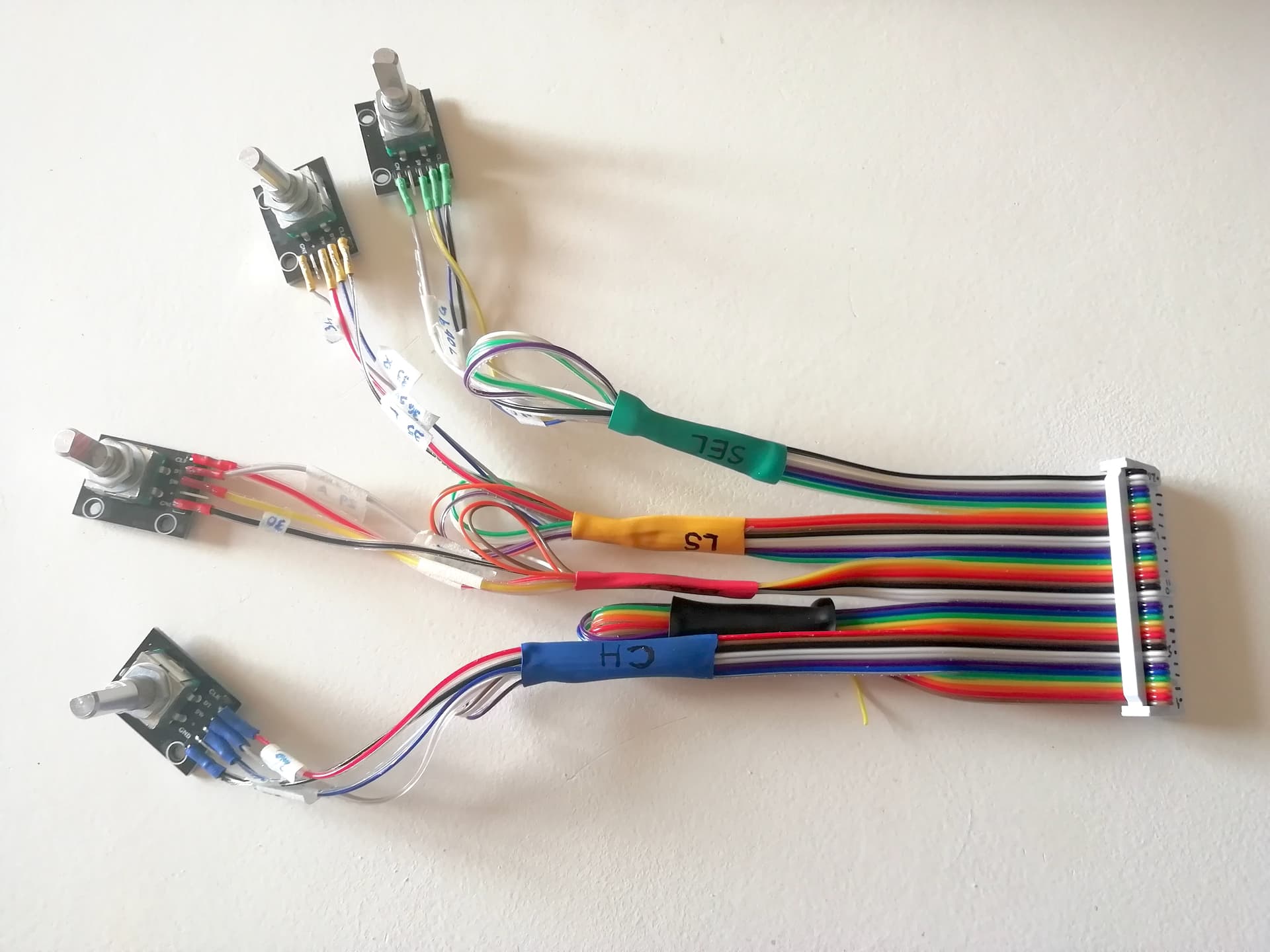
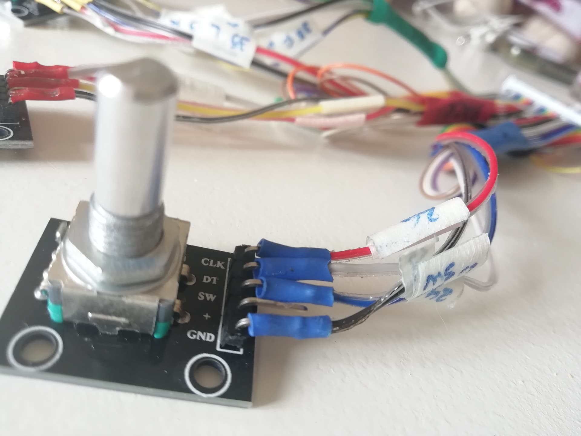
As you can see, I first labelled each cable one by one, testing continuity with the multimeter; then I soldered carefully (so much carefully at the extent of my possibilities as you can guess) and started to test, maintaining non used cables isolated, but ready for later use.
The supposed wiring that should work it doesn´t. Is giving RED ERROR all the time
By the way, when yesterday I faced the stacatto issue did not get a RED ERROR in any moment, obviously with gpio cable disconnected.
Today I burnt a fresh Zynthian OS, and tried again. The same result: RED ERROR.
Even I tried putting -zero- on encoder pins A & B for trying only switches. I got some random results, but only on switch LS, which worked sometimes when clicking on.
I must say than before, I tested the 4 encoders with multimeter as your recommendation, and it all seemed to work fine, buzzing when rotating clockwise with contacts on outer pins. I could then aware that to get sounding when in counter clockwise, I had to change to the other pin ![]()
Now I will show some pics of my design. I will start explaining why I got a PI 400. Basically for a question of thermal performance. I read in several webs that PI 400 did not need any kind of cooling, which was great to avoid noise.
So I began with Zynthian OS on it. After my first impressions, really positive, I decided to give it an enclosure. I found an interesting option, precisely with a PC fan cooler, as showed in next pic
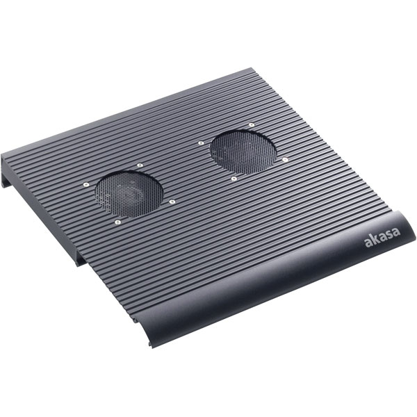
I bought a second hand -and only 4 bucks- AKASA fan cooler. Made of black solid aluminum. In the 3/4 view, you can see a kind of box below. That box it has enough room to allocate the PI 400 + cables. On the rear only 2 USB3 connectors. I want to make all connections needed inside the box(screen; encoders, and so on) letting only power supply connector and USB out to connect keyboard & audio card. Simple.
I have to cut a rectangle for screen (which need to be fitted somehow to aluminum) and 5 holes for encoders + a volume button. Perhaps a tiny hole for a LED working , when device is on, though not decided yet.
Now I will show the initial facing ideas to implement design over AKASA
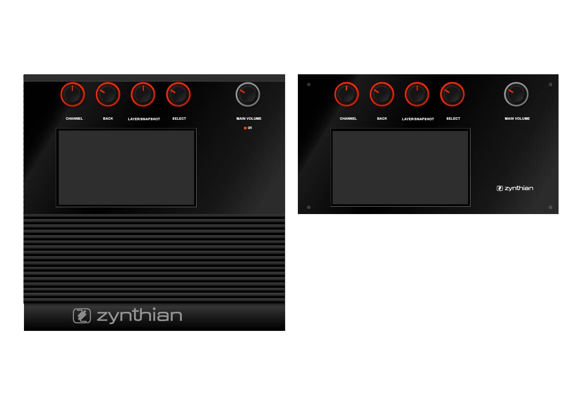
The left shows a design with minor alterations of the surface itself. I like it but is some bulky: 30x30 cm. The second option 30x16 cm is a cut down, cleaning all the aluminum out the inner box to reduce the size. Over the top, a plastic bi-color BLACK/WHITE with laser engraved texts, will occult all the cuttings while giving a neat aspect.
After talking with @riban about if encoders should be placed left or right for right or left handed people, I came to the conclusion than top was the optimal position for any kind of user. So I placed them over.
To end this “large speech” when you asked me about switches, I have to say that initially I didn´t think in them, because could not find an implementation GPIO direct. But, as I told you before, I am reading interesting topics so in raspberry as in arduino and cannot discard anything.
The only important thing to me now, is get working the 4 encoders of apocalypse… ![]()
![]()