After tweaking around and enjoying my Zynthian project: Raspi 400+UMC404hd+7” HDMI-USB screen, I want to share some insights at the time that look for some help.
Yesterday I was very busy trying to load some new samples in Sfiz. My interest was to convert some AKAI piano CD’s into Logic. I did in EXS24, and after export them in exs format, I did convert through EXS2SFZ to SFZ. Finally I got to work and was a really pleasant moment. I was able to get working a piano sound of my interest into Zynthian. A dream made true!
At the same time, I have been able to work with touchscreen and keyboard alone. No mouse attached. However… encoders where put on design for a good reason: SPEED.
So I am wondering if, is there any simple way to attach encoders to my setup?
If not wrong, some spare parts on zynthian shop are soldout, and some posts I have read are a bit difficult to develop. I can soldering but my electronics knowledge ends at the tip of the soldering iron
The zynaptik board allows you to add encoders with a 40 way ribbon cable connection from the pi which is probably the easiest way of doing this and the encoders can be sourced as a kit so that’s one of the easiest ways of doing it and it’s official as well!
With the greenheart release in testing there has been a lot of work on control of a zynthian remotely using Midi and qwerty keyboards and these work very effectively from arduino’s using usb which is another way of implementing encoder control.
No, that is of little use. If you want to emulate the behaviour of the default 4 rotary encoders then you need endless encoders. The link you posted has end-stop pots. You can connect encoders like these directly to Raspberry Pi pins.
Sorry - no time to look now but search the forum. It has been discussed a few times. Our friend @wyleu has some experience of adding encoders directly to pins and others have too. It involves choosing pins that are not in use for other purposes. A common ground feeds the centre pin of each encoder and one side of each switch. (The encoders have push switches on their shafts.) The remaining 12 pins (2 from each encoder and one from each switch) need to connect to free GPI pins on the Raspberry Pi.
You might wanna use my recent approach on my first build, if you’re looking for more of a “lego bricks” level of engagement when doing the electronics and you’re less concerned about “cool slick looking box” as an outcome. It ends up just as fiddly in the software, but doable.
I bought cheap encoders on aliexpress (the kind on a circuit board with pins, which they expressly do not recommend here lol) and wired them into a Teensy (any microcontroller device that can do native USB hosting is fine - this includes Teenies, a number of Adafruit Feather devices, Arduino Pros and a number of others, you can get one cheap) and hacked up a set of working encoders without too much hassle using a couple of their libraries.
On the zynthian end, you need to do a number of things, including switch to the testing branch, enable master channel, and add the CUIA actions for the encoders up and down into the configuration, on specific sequential notes starting at E1. Might be another step or two, can’t remember exactly, but the point is, this can be implemented easy and cheap with an absolute minimum of soldering, if you buy the right parts.
My code is on github and I could walk you through duplicating what I did, basically the code only works if you configure everything the same way I did, if you don’t you’re gonna have to start modifying the code and good luck to you lol. But I do have a fully functional zynthian v4 on my desk, more or less (the encoders don’t accelerate so there’s a lot of turning at this point sometimes).
But I’ve also, since getting my “stock” device put together, evolved on what I want to do with this. Once you can build your own midi controller to your own specifications, why bother with a one-panel-for-all configuration in any respect? It’s a wonderful and intuitive interface, but the whole point of Linux (literally, this is why it exists) is to give us complete control over our digital life.
So, now I’ve kinda wiped the board clean, and I’m thinking about what I want to have available when I’m playing music at the touch of a button/turn of a knob, and I’m just gonna build that, with one or more Zynthians under the hood, each configified to sonically service my specifical musical requirementations. You referred to getting the piano sound that is interesting to you - now, why not build the midi box that is interesting to you? If you’re gonna start getting your hands into the wires, might as well just build the life you really want. :>
Very interesting your approach: "You referred to getting the piano sound that is interesting to you - now, why not build the midi box that is interesting to you? "
I am seeing that will have to put my hands in some kind of circuit though that was far from my first intention. Now I have some kind of additional homework
Will study deeply all your suggestions.
My first idea using the raspi 400, was building an attractive case. For the purpose, initially thought that adding an –enough big screen– would bypass the encoders. At the moment of test such idea, could clearly see I was mistaken.
Now I have to advance and make some moves on respect. I will inform you all later.
When considering an holistic approach to the equipment that zynthian provides start with the power supply. It is the very core of what is going on and need to be considered, especially if other bits of kit are going to be hung on the rig.
Yep. I usually give the Pi its own supply and anything else that is capable of taking external power, gets it.
I bought one of these, and on my intended stage rig there will be an MC device plugged into the always on, which will handle powering up the pi, and have sufficient battery to power it back down gracefully under power loss.
Even then, there’s a LOT of garbage power supplies out there. Beware.
I have received the encoders that you recommended me.
Now I am in trouble. After reading many posts about encoders connected directly to GPIO, I have not found a clear and direct way to do it.
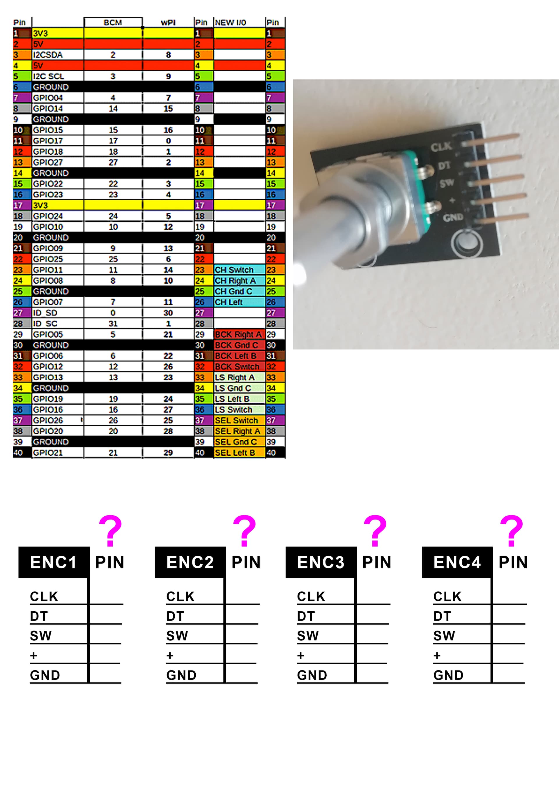
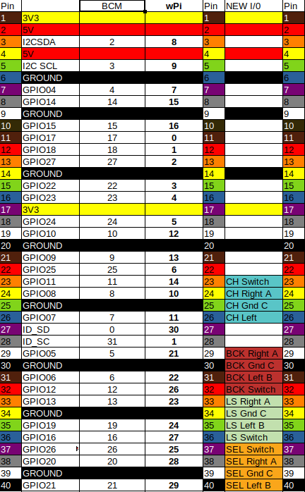
Please look at the next image. As you see I have 4 encoders with CLK, DT, SW, (switch I suppose) + (positive) and GND (ground). Ignore the meaning of CLK (clock?) and DT.
However the pin diagram recommended in several posts shown on the image uses terms as CH Switch, BCK, LS, SEL, etc which does not correspond to depicted on the encoders received. So I am kindly asking for a dummies guide to make it correspond. Sorry for my electronic-incompetence.
CH is Channel ( the original name for chain) top Left,
BCK is Back… Bottom Left
LS was Layer /Snapshot and is Top Right
SEL is Select Bottom Right.
As the person who drew up the chart above in all it’s colourful glory, I can, perhaps, shed a little light.
And explain some of the complications.
Firstly the encoder you have is not the possibly the one that is used on the zynthian in it’s initial state with 1/0 connection.
The normal one used is a simple pair of switches that connect to wires to each encoder to OV in a clever sequence that allows the 1/o pin to work out if the encoder rotary mechanism is
1/ not turning
2/ turrning left
3/ turning right
As you say the other connection is for the switch, but once again the zynthian 1/o pins for this switch are expecting to be connected to 0v ( or GND ) to signal that the switch ( a completely seperate device from the rotary component) has been pressed.
The four encoders where designed in this scenario to allow four grouped wires to be connected to adjacent pins on the 40 pin connector on the Pi.
So the group of wires and a ov go to the appropriate encoder.
If you have a multimeter available ( mine blew up yesterday … growl) You can test the encoder to see if it does indeed make the appropriate connections to 0v at the appropriate time. The switch should be open circuit when not pressed and at 0v when pressed.
The encoder can be checked by the continuity setting on the multimeter showing a series of brief connection that connect briefly as it is turned. across BOTH + & - pin and then checking the individual connections to OV on each side.
This is the grouping of the colours in the right hand column, marked New i/o
Again with a multimeter you can check the actual pins on the encoder itself and see which of the labelled pins they are connected to. I don’t know what the clk connection does.
The rainbow coloured pins are the pins of the Pi GPIO connector.
This gets the hardware connected but you need further information from the chart to configure the hardware configuration you have used to match what the zynthian expects…
.Ok. Just read @riban reply. He seems to recognise the encoder module so assume he knows better.
He’s right about the 12c pins but this was all inside a tiny case and it didn’t use 12c…
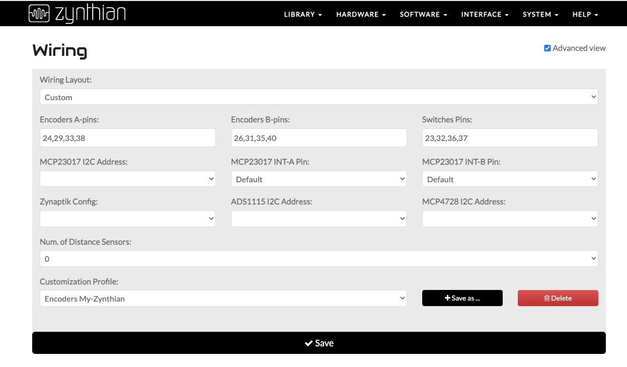
I also don’t know if the table is current I did have to change at least one pin, because something deep within the Pi changed and they no longer worked. The secret with getting it all going is getting one encoder working and work from there. The select is the easiest because it does the most work. BCK next, and then look at the top two. To do anything that isn’t approached logically get’s confusing quickly, and thats before you consider the two avaailable numbering sequences for BCM pins versus IO pins.
but nothing happens. I have tried several configurations found on the discourse zynthian, changing addresses but the only result got was a red error.
So I am guessing if I must procede to soldering the 4 encoders before getting a result? Or should have to work, with a different wiring settings? This is crazy! I promise, after make it functioning, I will make a dummies guide to connect encoders directly to GPIO