I’ve read a few posts about folks thinking about moving the 4x encoders off the GPIO to an i2c IO expander like the MCP23107. Has anyone actually managed this config before I go about reinventing the wheel? Thanks,
- Dave
I’ve read a few posts about folks thinking about moving the 4x encoders off the GPIO to an i2c IO expander like the MCP23107. Has anyone actually managed this config before I go about reinventing the wheel? Thanks,
Hi @beckdac!
As you can see, some people has gone this way:
The problem here is that @Imager implemented in pure python and made a bunch of modifications in the Zynthian UI main file to integrate his MPC23017 library. It’s a good work, but it’s not compatible with other layouts. Currently it’s not maintained and AFAIK, it’s a"dead fork".
Anyway, i love the idea and i would like to implement it inside the zyncoder library, extending the wiringPi library if needed, for initializating the MCP230XX IRQ lines.
Of course, if you want to work on it, you are very welcome and i would help you as much as i can. really!!
I don’t want another “dead fork” here, so we should work together for getting the best solution for Zynthian and of course, it should be backwards compatible with old-style layouts…
Kind regards!
Thanks! @Imager’s post was what got me on this track.
I’ve looked at the zyncoder library and I can see how to gut it to work with my setup, but what is less clear is how to make this change “backward” compatible with existing setups using GPIO, which I think would be the goal. Any thoughts on how to structure this before I get started would be great. I’ll work through it on my build.
Seems to me, we can modify this function in zyncoder so that it takes an additional argument which is the INT GPIO pin coming from the MCP23017 associated with the encoder if pin_a or pin_b is >= 100. The modified function would setup an ISR callback on the pin that would read out one or both banks of the MCP and do the encoder handling.
struct zyncoder_st *setup_zyncoder(unsigned int i, unsigned int pin_a, unsigned int pin_b, unsigned int midi_chan, unsigned int midi_ctrl, char *osc_path, unsigned int value, unsigned int max_value, unsigned int step)
Thoughts?
Hi @beckdac!
I think it’s better to create a separate function to setup the MCP230XX ISRs and associate with a GPIO pin.
No need to configure the ISR for every separate zyncoder, as it’s a “per-chip” configuration. It should be initialized in the “init_zyncoder” function.
As you can see, currently this function initialize the mcp23008 like that:
mcp23008Setup (100, 0x20);
Currently there is no ISR catching for mcp23008 and polling is used for switches. Probably this is too slow to manage “rotaries”, but i have not tried. Anyway, it would have poor performance and this is the reason we want to use interrupts 
I would add extra parameters for telling the function if we use the MCP23008 or MCP23017, and the ISR GPIO pins.
If the ISR GPIO pins are “-1”, then polling is used for switches (init_poll_zynswitches). If the ISR GPIO pins are >=0, then ISR functions will be associated (to implement!). This ISR function should read the corresponding ports, detect what port has changed its value and call the corresponding “update” function. Perhaps a “custom” update function must be implemented for optimal performance. In such a case, i woull try to abstract some code from the normal “update” function to avoid code redundance and improve maintainance.
Of course, i would help you as much as i can. Don’t doubt to ask!
Kind Regards!
OK, here is a link to the commit that implements MCP23017 based (4x) encoders and their switches with WiringPi ISRs on the MCP23017’s INTA and INTB:
Have a look and we can talk about how to move forward with changes towards a pull request. There is room for four more switches or one switch and another encoder or… Basically four unused pins on the MCP23017.
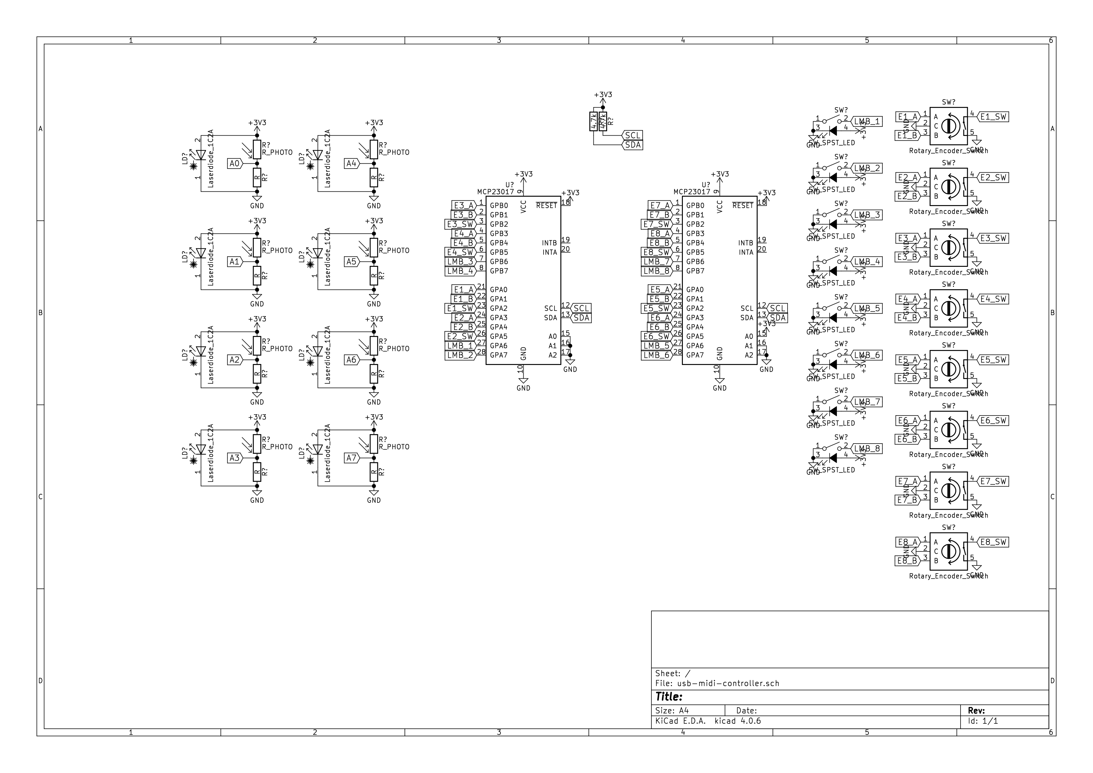
Schematic for the setup is here:

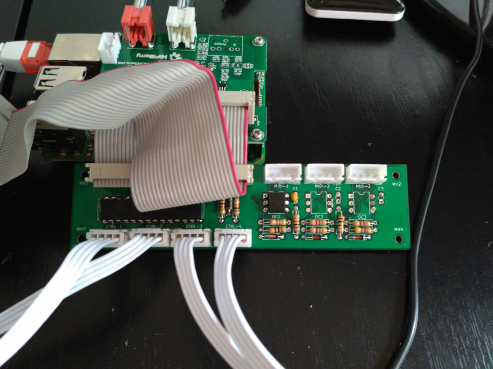
I’ve implemented a functional prototype as shown here:

Greaaaaaat @beckdac!!
I’m in Berlin for a few days. As you probably know, @C0d3man & friends have got a stand in the Maker Faire Berlin 2017, so we are showcasing the Zynthian project here. I will come back to Barcelona on Tuesday and will test your development ASAP.
Gutten Regards! 
Nice work @beckdac.
I only wonder how this fits with the big picture of your USB connected switches, @jofemodo.
Wouldn’t it be better to use this controller with a USB Interface, so that you can chain them?
Tell me, if I should integrate his wiring as selectable option in the webconf.
Freundliche regards, 
Markus
Quick note: under this setup, an encoder’s A and B pins must be on the same MCP23017 bank.
@mheidt, I have an external controller based on Teensy 3.2 that has 8 encoders, 8 buttons and 8 air guitar strings. Is that what you are referring to? The schematic for that is here:
Nice!
Guess, it should be possible to mix rotary with normal push pads as well.
Then we need a dynamic configuration and new features like midi/audio file playback and map those to the buttons.
Hi @beckdac
In your schematic pins 19 and 20 (INTA and INTB) are the GPIO ports 25 and 26 connected?
I’m working on a single board for my Zynthian with all midi connections and encoders too.
Congrats for your work! Here in Brazil I can not find the MCP23008, I will try to use the MCP23017 too!
Regards, Rod.
They are WiringPi ports 27 and 25. WiringPi has its own “portable” numbering. This pinout chart shows how to map the the WiringPi to the recent GPIO pin header in parens next to the BCM pin #:
Another quick note. I included 4.7k pullups in my original prototype and it works fine. However, the Raspberry Pi 3 has 1.8k pullups on those lines so in practice on my prototype the final pullup resistance is 1.3k which is above the minimum for fast mode so there is no problem with the rise time. When I build another, I will leave off the external pullups. I have removed them from the schematic.
Hi @beckdac!
Finally i had some time for testing the new “All-In-One” PCB, that includes the MCP23017 for the encoders+swithes and MIDI IN-OUT-THRU based in the @Imager’s circuit, using H1L11 optocouplers.
The controllers part works like a charm with your new code. I didn’t need to change a single line. You made a very good work, man!! Thanks a lot!
FYI, i’m testing without external pull-ups, and using the Zynthian Controller PCBs with “capacitor-to-ground” for debouncing: 100nF for switches and 10nF for encoder pins. This is really simple and works quite well. The software debouncer almost don’t need to work.
I hope to merge your changes into the master branch ASAP, so please, make a “pull request”.
In the other hand, i made a stupid error in the PCB design and MIDI-OUT & THRU are not working. You can use it to fry an egg, but not to do MIDI stuff with it, so i’ve removed the optocoupler and fixed the PCB. Now i’m awaiting for the new ones to arrive … 
Super Regards!
Can we still use different kind of displays?
Having the waveshare32 and it’s special wiring in mind.
Of course! The main reason to move the controllers to a GPIO expander is easing the configuration of hardware devices like displays and soundcards by avoiding “pin collisions”.
The new All-In-One circuit only uses I2C and the GPIO 25 & 27 (pin 35 & 36) for interrupts. This 2 GPIO ports are rarely used by any device. If you know some device using it, or you think there is a better choice, speak now, please!!!, before i order a few hundred of PCBs!
Regards!
So that’s 2 Pins for 12C and GPIO 25 & 27 plus +V ( 3.3V or 5V? or both ) and ground(s)
Anyone any idea how far that could be run before you need to start buffering it . . . ?
I’d like to break out the encoders into a separate enclosure. . .
Well just cos really.
HI @wyleu!
I think it should be perfectly possible to have a few meters. it depends of I2C frequency and cable capacitance. If needed, you can change the I2C frequency tweaking the config.txt, like that:
dtparam=i2c_arm_baudrate=xxx
Just try and give feedback
Regards!
I used i2c connection up to 2 meters, and never had problems.
But, as @jofemodo said, you can lower data rate if you have errors.
That sounds about right for what I’m invisaging…
Have we any idea when the new encoder board will be available and what the price might be?