Getting encoders to work on a DIY-Zynthian

Encoder bei einem DIY-Zynthian zum Laufen bringen

Hallo liebe Musiker- und DIY-Gemeinde ,

ich wende mich heute mit einer großen Bitte an euch, weil ich an einem Punkt angekommen bin, an dem ich alleine leider nicht mehr weiterkomme.

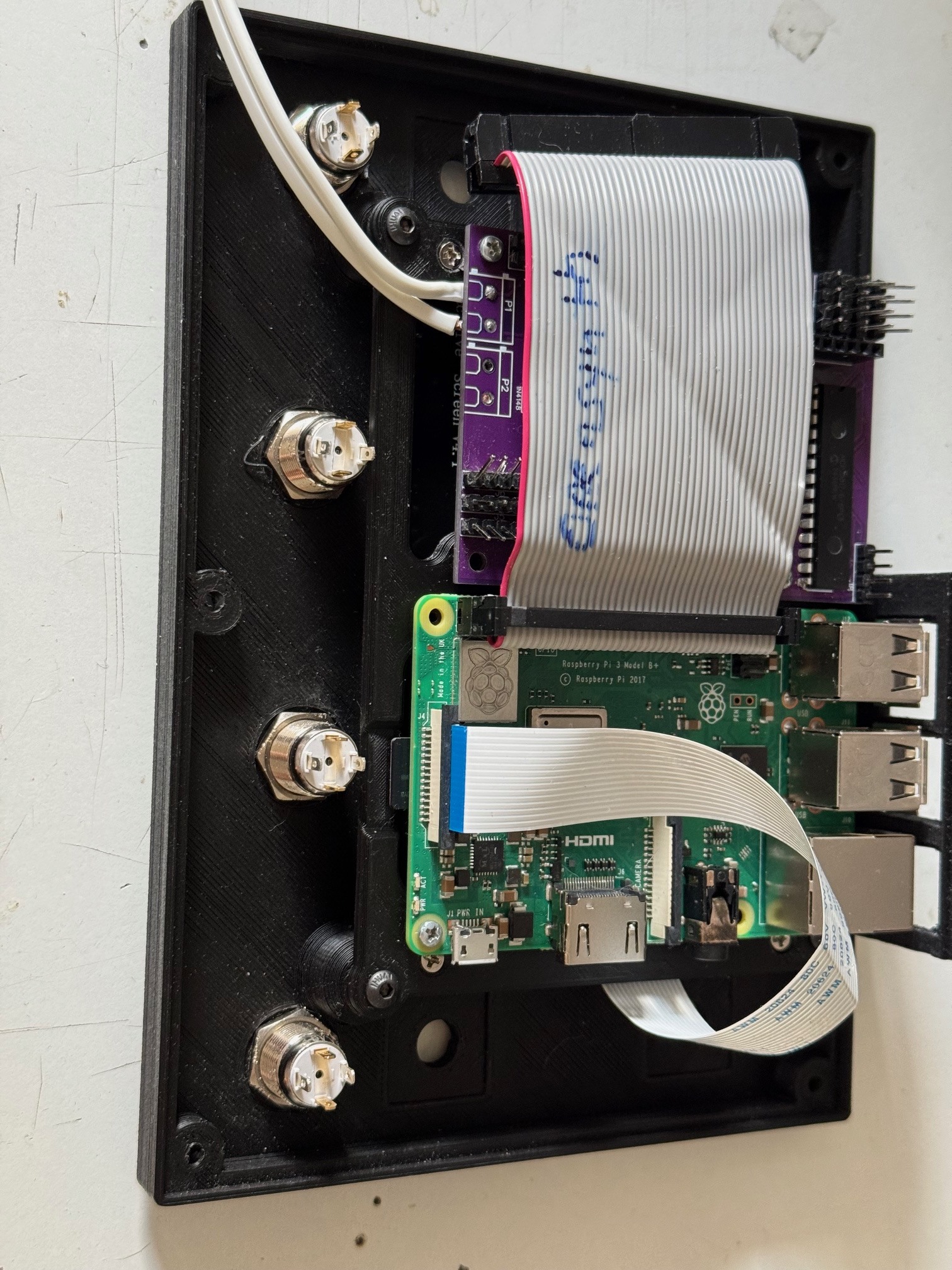
Aktuell arbeite ich an einem DIY-Zynthian-Projekt, das ich so weit wie möglich selbst aufbauen und verstehen möchte. Als Basis nutze ich derzeit einen Raspberry Pi 3 B+, der später – sobald alles stabil läuft – durch einen Raspberry Pi 4 mit 4 GB RAM ersetzt werden soll.

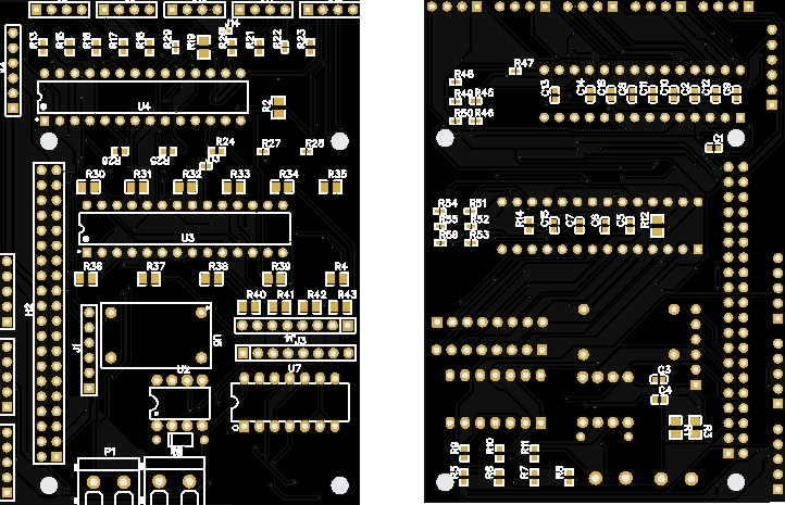
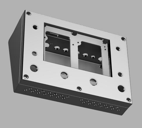
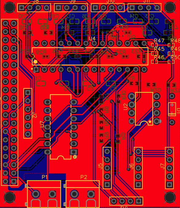
Dazu habe ich ein eigenes Board entworfen und fertigen lassen, das folgende Komponenten enthält:

  • 6N138-020E Optokoppler für den MIDI-Eingang

  • SN74HCT14N für MIDI-Thru und MIDI-Out

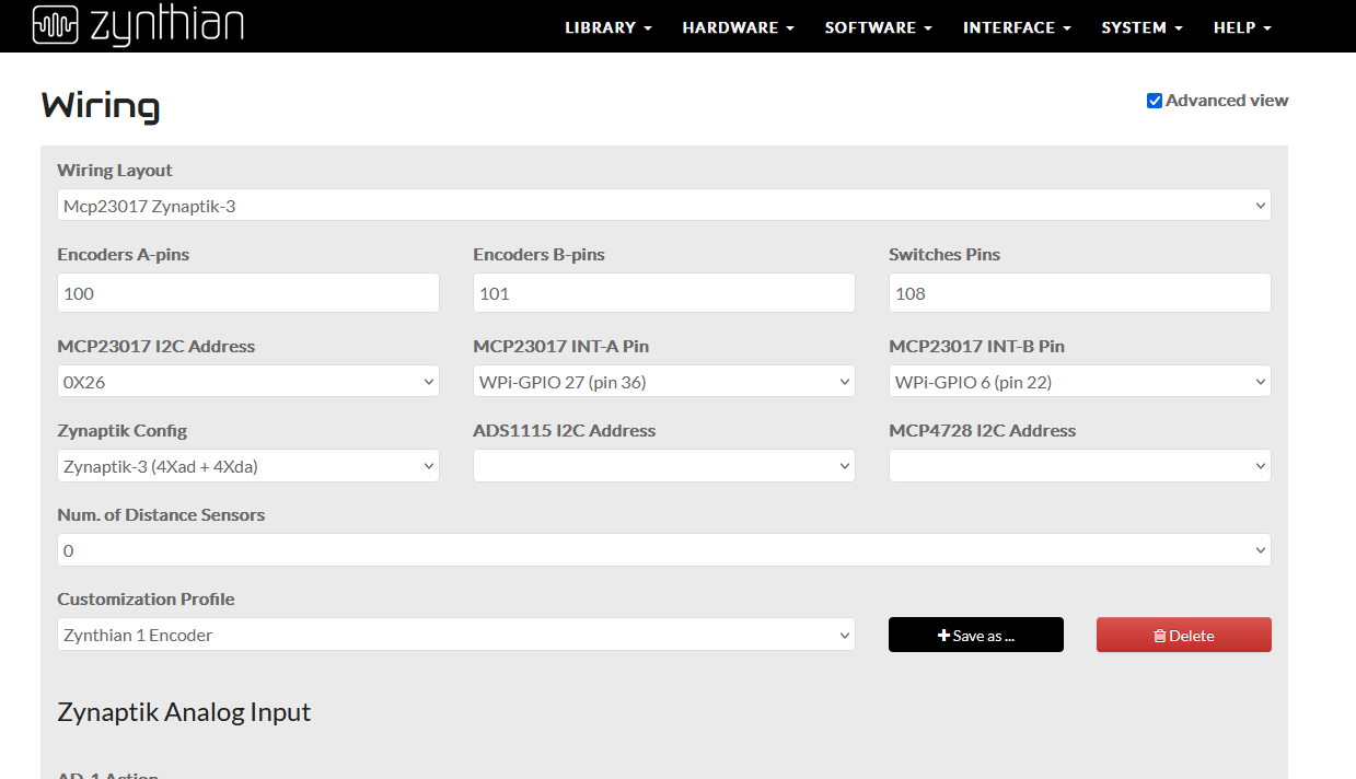
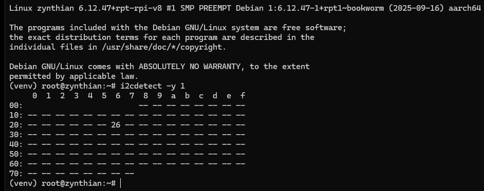
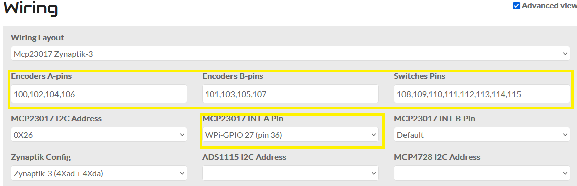
  • 2× MCP23017-E/SP für Encoder und Taster

Zusätzlich gibt es Steckplätze für:

  • einen PCM5102 als DAC

  • einen PCM1808 als ADC (aktuell eher als Vorbereitung – ob er letztlich nutzbar ist, ist noch offen)

Der Aufbau ist inzwischen vollständig bestückt und getestet. Leider stehe ich nun vor folgendem Problem:

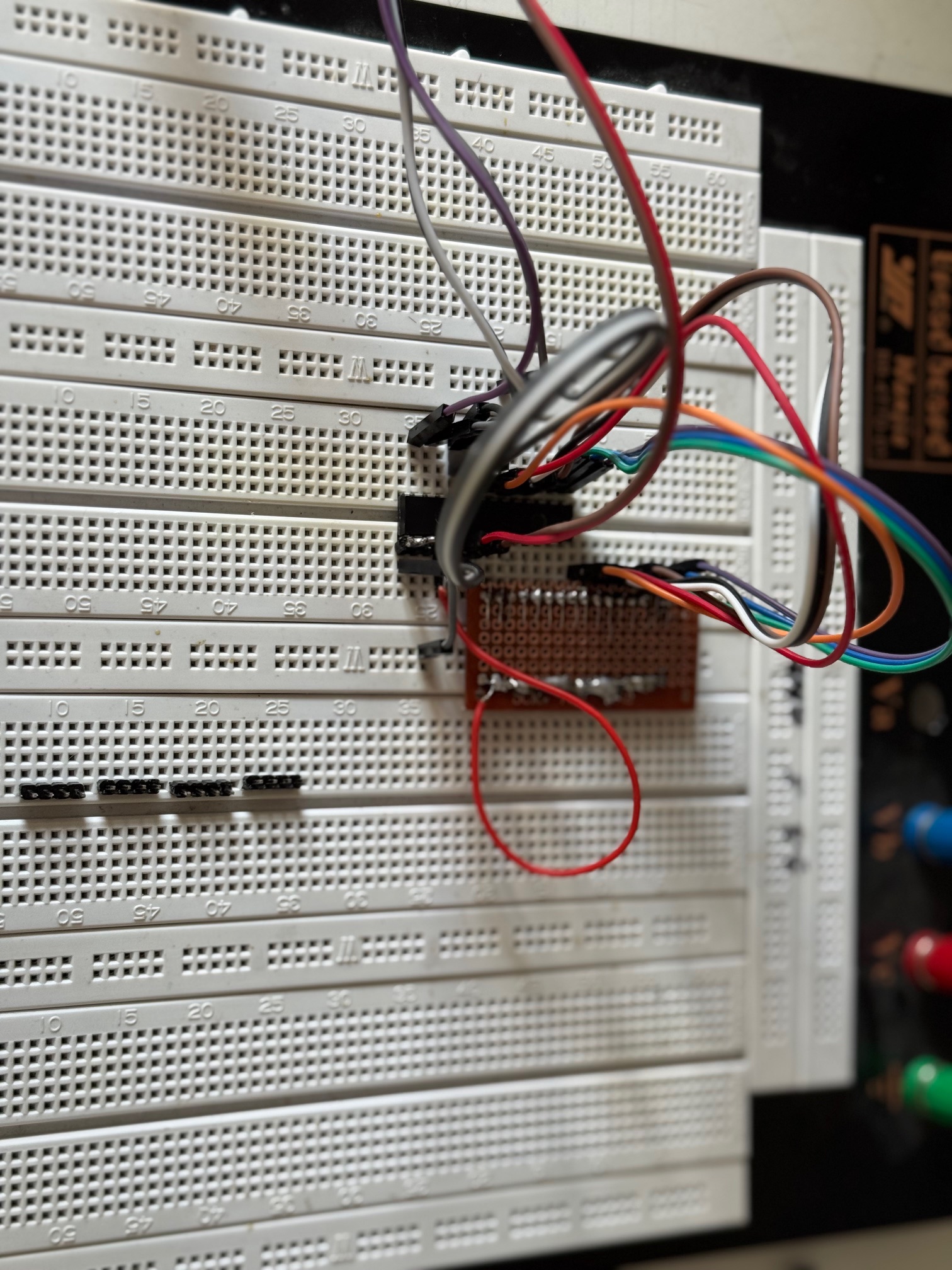
Die Encoder lassen sich über die MCP23017 nicht zum Laufen bringen.

Ich habe bereits einiges ausprobiert:

  • alle Eingänge mit 22 nF Keramikkondensatoren entprellt

  • zusätzlich 10 kΩ Pull-up-Widerstände eingebaut

Bis jetzt leider ohne Erfolg.

An diesem Punkt hoffe ich sehr auf eure Erfahrung und Unterstützung. Vielleicht hat jemand von euch schon Ähnliches umgesetzt oder erkennt auf Anhieb, wo der Fehler liegen könnte. Sollte sich herausstellen, dass meine Platine einen grundlegenden Fehler hat, bin ich absolut bereit, eine neue Revision zu erstellen – wenn es am Ende eine funktionierende, saubere Lösung ist, ist das für mich vollkommen in Ordnung.

Als kleines Dankeschön möchte ich mich gerne revanchieren:
Wenn ich mit eurer Hilfe das Projekt erfolgreich zum Laufen bekomme, verschenke ich eine unbestückte Platine der final funktionierenden Version des Synthesizers. Alle Bauteile sind lötbar (SMD-Widerstände und -Kondensatoren, noch gut mit Pinzette machbar), und einige der Kleinteile, die ich ohnehin zu Hause habe, würde ich ebenfalls dazulegen.

Vielen lieben Dank fürs Lesen, fürs Mitdenken und für jede noch so kleine Idee oder jeden Hinweis
Ich freue mich sehr über eure Rückmeldungen!

Herzliche Grüße
Manuel

Traditionally this has been an English only forum.
So please do not be offended by replies, predominantly in English.

1 Like

Schematic_Zynthian-mit-Pullups-für-Encoder_2026-02-07.pdf (150.2 KB)

2 Likes

English, please

Sorry, happy to try again in English.
Getting encoders working on a DIY Zynthian

Hello dear musicians and DIY community,

Today I’m reaching out to you with a big request, because I’ve reached a point where I unfortunately can’t make any further progress on my own.

I’m currently working on a DIY Zynthian project that I want to build and understand as much as possible by myself. As a base, I’m currently using a Raspberry Pi 3 B+, which will later be replaced by a Raspberry Pi 4 with 4 GB RAM once everything is running stably.

For this purpose, I designed my own PCB and had it manufactured. It includes the following components:

  • 6N138-020E optocoupler for the MIDI input

  • SN74HCT14N for MIDI Thru and MIDI Out

  • 2× MCP23017-E/SP for encoders and buttons

In addition, there are sockets for:

  • a PCM5102 as a DAC

  • a PCM1808 as an ADC (currently more as a preparation – whether it will actually be usable is still open)

The board is now fully assembled and tested. Unfortunately, I’m facing the following problem:

I can’t get the encoders to work via the MCP23017.

I’ve already tried quite a few things:

  • debouncing all inputs with 22 nF ceramic capacitors

  • adding additional 10 kΩ pull-up resistors

So far, unfortunately, without success.

At this point, I’m really hoping for your experience and support. Maybe one of you has implemented something similar before or can immediately spot where the problem might be. If it turns out that my PCB has a fundamental design flaw, I’m absolutely willing to create a new revision – if the end result is a working, clean solution, that’s completely fine for me.

As a small thank-you, I’d like to give something back:
If, with your help, I manage to get the project running successfully, I’ll give away an unpopulated PCB of the final, working version of the synthesizer. All components are solderable (SMD resistors and capacitors, still very manageable with tweezers), and I’d also include some of the small parts that I already have at home.

Many thanks for reading, for thinking along, and for every little idea or hint.
I’m really looking forward to your feedback!

Best regards,
Manuel

2 Likes

Probably best to start with a couple of photos to give us some context.

Can you see the 23017 in i2cdetect -y 1 or i2cdetect -y 0 ?

Also handy if you post the current version you are on. Perhaps grab a screen shot of webconf. It tells us much.

1 Like

Hello Wyleu, thank you very much for your reply. Attached are the pictures of the configuration and the setup. I suspected an error on the PCB, and therefore I built a 23017 on the breadboard.

I find the 23017 on i2cdetect -y 1

Attached is also an image of the housing.

1 Like

“I’ve made a few more changes to the configuration.”

I translated the title of this chat to English.

2 Likes

It still doesn’t work. Do I need to change any settings in the menu shown below? I’m unfortunately a complete beginner when it comes to Raspberry Pi and Linux. I really need your support, please.

#

Many thanks for your support. :slight_smile: :smiley:

1 Like

Hi Manau,
it seems you have similar problems than I had.
Maybe there are some enlightments for you reading this post:

There is a history of my attempts and people trying to help me.
I must confess that I made some stupid errors on the way. Finally I got 4 encoders to work. The 20 buttons with the second port expander are still waiting.

I am a bit surprised that your I2C bus shows address 0x26 = 2*16 + 6 = 38dec.
Why didn’t you choose 0x20 or 0x21 ?
But it should be no problem as you entered it correctly in the setup.

Can you post your schematics?

I still do not understand everything that is important, though I dived deeply into some of the software modules. What I have understood is that the C components are freshly compiled when a change in the config is done.
Another thing is that config V5 has a special status. Everything is coded in the zyncontrol_v5.c, whilest the other use zyncontrol_vx.c (finally I understood that vx meant v1, v2…, didn’t get it at the beginning)

Ah, by the way, you only configured the interrupt for port A.
What about port B?

1 Like

In such a situation as yours, hardware is probably the first place to look. It’s very easy to get caught bouncing back and forth between hardware and software.

As I understand it you designed the board. Presumably you prototyped it to some extent?
It’s always difficult to gauge peoples level of experience but to get boards manufactured indicates intention, and for that well done!

Are you absolutely sure of hardware? ( in which I include the MCP23017 )
You have the i2c connection working which is excellent, because it ‘sees’ the chip and you’ve matched the address for the basic connection.

Are the switches and encoders putting the correct signals onto the MCP’s pin’s ?

This is actually a peculiarly difficult element to fault find because without tearing apart i2c packets there isn’t too many ways of deciding if the problems are upstream or downstream of the i2c connection.

Perhaps we need a check the pins routine somewhere in the increasing mountain of zynthian helper functions?

The other element is of course interrupts. There are two of them. A lethal opportunity to get them reversed. Always needs checking emphatically, but again hard without careful knowledge of what they do.

IF you have i2c connectivity it’s probably safe to assume the internal registers of the MCP23017 are properly populated, but worth checking. But again this is hard, without a contrived code hook up to read the values over i2C.

AS ever it’s worth starting with the 3rd Encoder ( select) switch, which is zynthians equivalent of an Enter key.

Concentrate on getting that working and then you have repeatable checks for hardware and software, and can learn the intricacies of the pin mappings with some degree of peace.

”a complete beginner when it comes to Raspberry Pi and Linux”

Don’t worry many people end up here from a desire to do something specific musically and are having to learn by association.

It’s also fascinating what one can learn when having to learn in a completely different field as it allows a new appraisal of what you already knew in your initial field.

The odds are there is a problem on the board. The difficulty is it isn’t at this point known to be functioning and so you could well have some alterations to make.
Symmetry is one of the hardest things to get your head around in PCB design and whilst reversing a 16 bit bus is perfectly possible and can lead to connectors being the wrong way roun, it is frequently the little 3 bit busses that are most easily reversed. But above all before all this check your power supplies onto every pin and component.
Continuity first, then voltage. Look for voltage dips from Power Supply. Often an indication of something passing rather more current than it should.

A thermal camera can be a useful fault finder, if you have access to one.

Keep at it, and make lots of notes.
Also prepare yourself for this . . . .

1 Like

Schematic_Zynthian-mit-Pullups-für-Encoder_2026-02-09.pdf (154.7 KB)

This is the latest version of the schematic. I haven’t ordered any PCBs based on this schematic yet. I will only do so once I have a working BETA.

I used AI assistance when creating this schematic. I was told that certain components were not necessary. Now I know very well that AI can make mistakes too. It is helpful, but everything has to be checked carefully.

The addressing was also recommended by the AI. In hindsight, I should have relied more on your forum during the development of the PCB, and on the information provided by the creators of Zynthian.

Indeed. I have turned a whole circle with the Chat Mistral (I prefer European AI, if I use any), who told me many different “wisdoms” about pin adressing, and at the end I was at the beginning again.
What made me dizzy was the many different hardware and software configurations.
For example it took me some time to realize that V4, V5 … had nothing to do with the Raspi version.

Concerning your schematic I see 2 port expanders. The addresses are set by the 0 Ohm resistors R47…R51 (I suppose you have enough electronic skills to know there can only be one ton ground or to plus, not both). If you want address 0x20, all must be connected to GND. For 0x21 A0 must go to plus, the rest to GND. However for 0x26 as you had it, you have it, A0 → GND, A1, A2 to plus.
Sorry if I repeat things that you know, I have no idea about your electronics skills.
If you tell us about your specific address wiring, it will be easier to help.

Hi Jean-Claude, thanks a lot for your message.
The parts R47 … R51 are not meant to be used as actual resistors, but simply as solder bridges to make addressing easier. It’s basically a prototype-style solution.

The first MCP23017 is set to address 0x20 and the second one to 0x26.
My plan is to rebuild everything using just one MCP23017 on a breadboard, with pull-up resistors.

My electronics skills are strictly hobby-level – I’m very much learning by doing.
Same story with my CAD skills :slightly_smiling_face:

After some new insights, I have slightly reduced my requirements. This resulted in a PCB. I have checked it manually for errors. However, I will only know for sure whether it works once I have assembled one.

This version now uses only one 23017, and I have completely omitted the PCM1808. I will get back to you once I know whether it works.

I am attaching the Gerber files here for you. Please note that this is open source and provided without any warranty. With these files, you can have a PCB manufactured anywhere. I personally use JLCPCB. They are good and affordable, also offering fully assembled systems and worldwide shipping.

So have a nice evening.

Yours

Manuel

Gerber_Zynthian-mit-Pullups-für-Encoder-LC_PCB_Zynthian-mit-Pullups-für-Encoder-LC_2026-02-09.zip (119.4 KB)

1 Like

The PCB is configured so that a 40-pin female header can be soldered on, allowing the PCB to be simply plugged onto a Raspberry Pi. I use a ribbon cable because it results in less height, making the overall system flatter.

1 Like

This PCB is only 5.5 cm by 6.5 cm in size. It is ideal for installing it, for example, into the housing of a Studiologic master keyboard, or for use in other compact systems.

1 Like