THere has been some debate concerning the MIDI schematics for the zynth…
Presumably you’ve had a look at https://discourse.zynthian.org/t/zynaptik-midi-status-led-pinout/4148/7 ?
I assume you are working with this circuit. You say you find code intimidating, but don’t worry I doubt there is any code involved in this issue, as code can only do what the hardware lets it, and the likelihood is your problem is hardware. . .
Firstly do you have any way of checking electrical connections like a multimeter? That would certainly help because although it’s a good visual inspection will often reveal problems there real proof is finding out where electrons actually go in a circuit. It’s not difficult to get a tiny piece of dirt or grease on the point where two metal surfaces meet which prevents electrons crossing the gap and that’s all that’s needed, but these sorts of things are really only an issue when you start cos once it works it tends to stay working. . .
So with that in mind lets look at the circuit.
MIDI IN is the one that needs the most protection from dangerous conditions as it’s really nothing more than a sensitive electrical input, and with the likes of those ghastly ham fisted radio gorilla’s around it’s perfectly possible that some unpleasant voltage will get plugged into a circuit destroying the sensitive and sometimes expensive components. We also don’t want a direct electrical connection between those horrible voltages and our circuit because that can produce hum, for various reasons I won’t go into, or can in really horrible circumstances give people significant electric shocks if other kit is miswired, so the people that designed MIDI included the opto isolator to address this. Its the H11L1 chip and it is as it’s picture describes a little LED next to Light sensitive component. notice that there is no electrical connection between the circuit input side ( the Left) and the bit that does the switching ( the right). ie. isolation !
You say the LED does work. Well that great cos it means a fair bit of the circuit is ok.
The LED is connected between pins 1 & 2 and as is said on the thread I pointed to it’s actually part of the circuit.
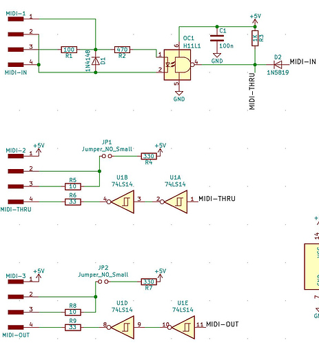
The MIDI in ‘signal’ comes in at pins 3 & 4 and thats probably not the best way to think of it. Rather it’s more like a switch that is connected between those pins and it closes to send one binary signal and remains open to send the other which is connected to the source of electrons in the device that is transmitting the MIDI . In effect it’s shorted out, and the current, when the LED is on comes from the MIDI device’s MIDI out socket.
So we prboably assume that R1 and the Diode D1 ( which is there to prevent problems if the MIDI signal coming in is connected the wrong way round, a common mistake). Now it is possible that you have both the MIDI in connection the 'wrong way ’ up AND your LED might be the wrong way round so that’s worth checking. You don’t say what you are using as a MIDI source but if it’s something commercial it’s probably ok, but worth thinking about.
From here on in it’s really about connections. if you have got a multimeter check the connection through to the pins on the Opto Isolator and make sure there are actual electrical connections because that would mean the LED could light but electrons are not flowing thro’u the opo’s LED so nothing will happen.
ON the other side of the opto we could also have problems of lack of connection. The electronics don’t care they only do what electrons want to do. You might have a dead opto isolator, and that you can’t rally tell without testing it or substituting another part, or there might be a dry solder joint ( a connection that looks dull rather than shiny and doesn’t look like the solder flowed properly) that doesn’t conduct, or ,and most people have done this at least once, an IC pin is folded up under the body of the chip and doesn’t actually go into the hole or the socket that is’ meant to.
A careful inspection with a magnifying glass will often reveal this sort of thing, and if it’s a dry joint, a dab with a soldering iron will sort it out.
Again if you have a multimeter check that there is 5V on pin 6. if the capacitor C1 or REsistor R3 were short circuited ( not very likely but … ) then the chip wouldn’t work,
if you have spare LED and resistor you could use that to check to see if there is a signal ( LED on & off ) at pin 4.
And finally there are the ribbon connectors. THE MIDI IN signal isn’t actually handled by other chips on the xynaptik board it is transfered directly to pins on the Raspberry Pi itself (pin 10 on the Pi connector). again if you have a multimeter check the continuity to the pin on the Pi ( this can be a bit hard to do as you really need to work out whichpin is pin 10 and the nmake an electrical connection to it. But ribbon connector connections are at the root of many electrical problems and it’s possible that the ribbon connector doesnt make a connection for some reason or other. They are amaxingly good and have been improved ver years but it’s still 40 parralle electrical connections and it doesn’t need much to stop one connector working.
Do all your encoders work? It’s posible to offset a ribbon connector by one pin or miss an entire row when plugging it together. Again a good inspection assuming things are wrong will often show something up.
This is very long lump of information and doesn’t specifically indicate a direct fix, but it hopefully will give you some things to investigate to address this problem. Photo’s are also a great help, if nothing more than confirming the overall health of the components ( Oh i didn’t realise that big crack on the board might be a problem sort of thing )
Take a photo and if you can get it onto the computer you browse this thread with and just drag and drop it int the thread will allow us to see what’s going on.
So in summary
- Photos
- Visually Check ribbon cables
- Visually check circuit board
- IF you’ve got a multimeter check continuity and Power on pins.

 ).
).