The gpio pins have changed over time as the zynthian has evolved. The general recommendation is to us the msp23017 method as this is how the current encoders are implemented and althou the gpio methods are still supported there have been several changes from the pi implementation itself. The wiring I documented for my first attempts required changes in wiring when specific pins became inoperable due to low level changes in the pis gpio structure as we moved from Pi3 to 4 and onto 5.the pi 5 has also prompted changes in the libraries which add to the confusion. That’s not to say it can’t be made to work but there is no perfect implementation (from my experience). The best way to address it is start with the select encoder switch and get that working on a pin. You are unlikely to hit a perfectly working implementation on the first go and you will almost undoubtably have hardware issues if it’s the first time you get a soldering out in anger. You will also need to configure the software in the wiring config and you want to confirm basic functionality with just one switch before progressing. The two encoder pins on the select encoder will then allow you to get the entire select encoder functioning. That will give you enough insight to proceed to the others with enough experience to fault find things successfully.
But as I say there are cheap mc23017 boards available and Inow use those rather than straight gpio pins. The 23017 has the tremendous advantage that you are buffered from direct problems on the pi if there are issues.
Sorry I can’t give a specific wiring but this is more a case of simply adding to the confusion. I’ve built zynth with led encoders so it can be done but it’s a rather involved mess of wires unless you use a pcb to sort the connections out and if you do that you aren’t too far from using the 23017.
Im sure this reads as rather frustrating and a bit patronising, but fault finding a zynth that suddenly looses an encoder because of a change in a pi library is very frustrating as generly the first thing you suspect is your own wiring and that generally leads to increasingly surgical remediation to find a fault that has been introduced in some other area.
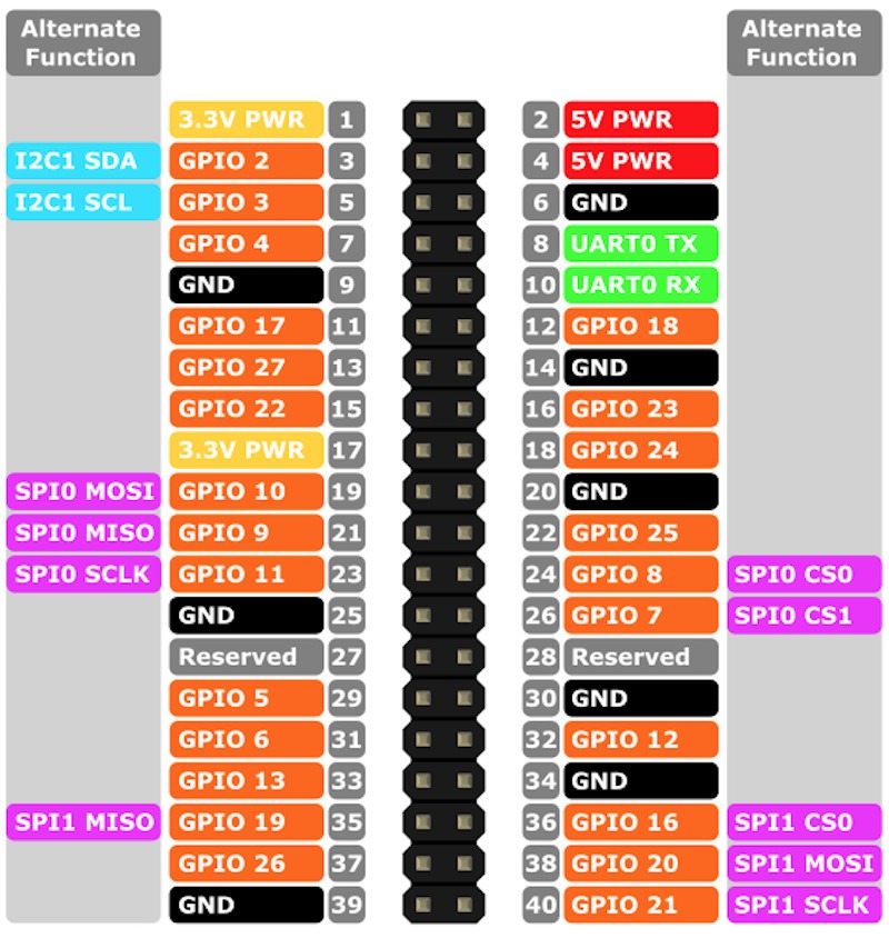
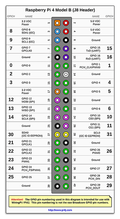
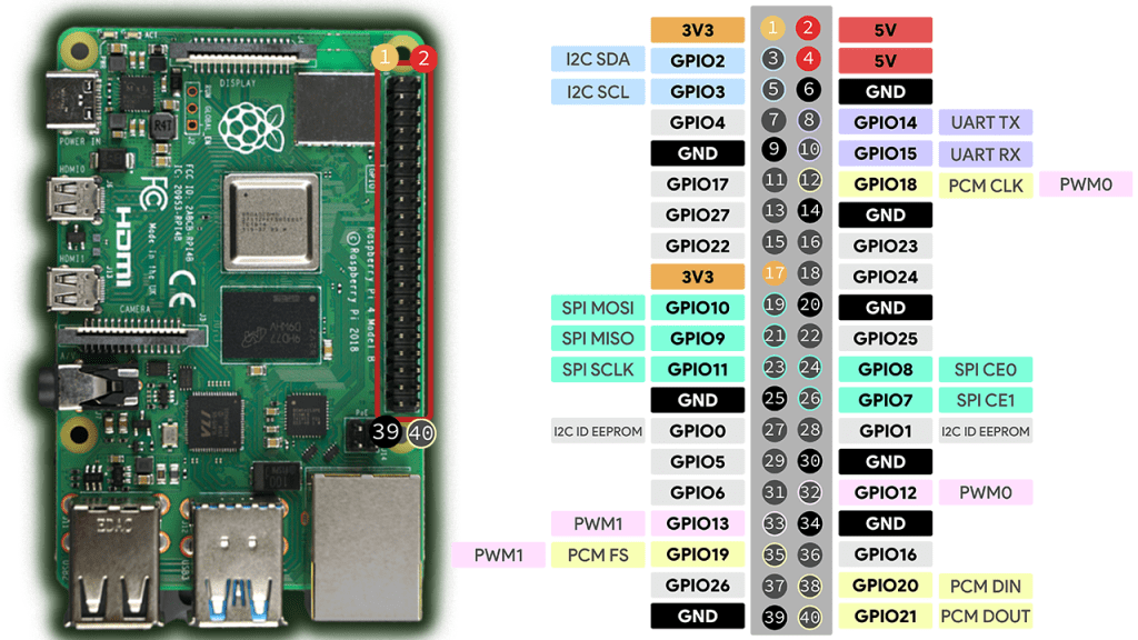
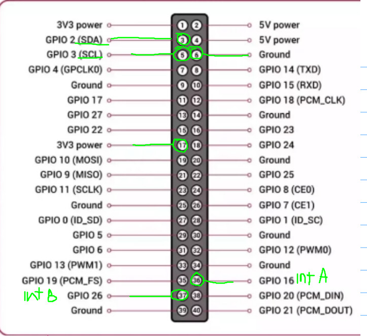
I sometimes found pages like this quite helpful. You’ll see that in your case on physical pin 36 the number 27 doesn’t refer to the GPIO number (16) but to the WiringPi number (27).
I have to second @wyleu about the MCP23017 solution makes it a lot easier because you don’t have to think so much about free GPIO pins other HATs and stuff might want to use. I use pin 36 and 37 alone for it (plus SDA and SCL of course).
Otherwise you may have to take care about GPIO your soundcard HAT, MIDI I/O, EEPROM and so on blocks.
I went through the whole process with the help of these wonderful folks here.
@trojanGoat I don’t know if you are trying to wire direct to the Pi or use a port expander but like Wyleu said, it’s best to use the port expander, it’s worth it in the long run. I think the link from Hannesmenzel has all you need but I’ll add my 2c here:
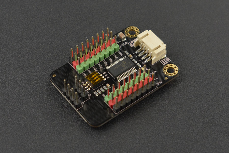
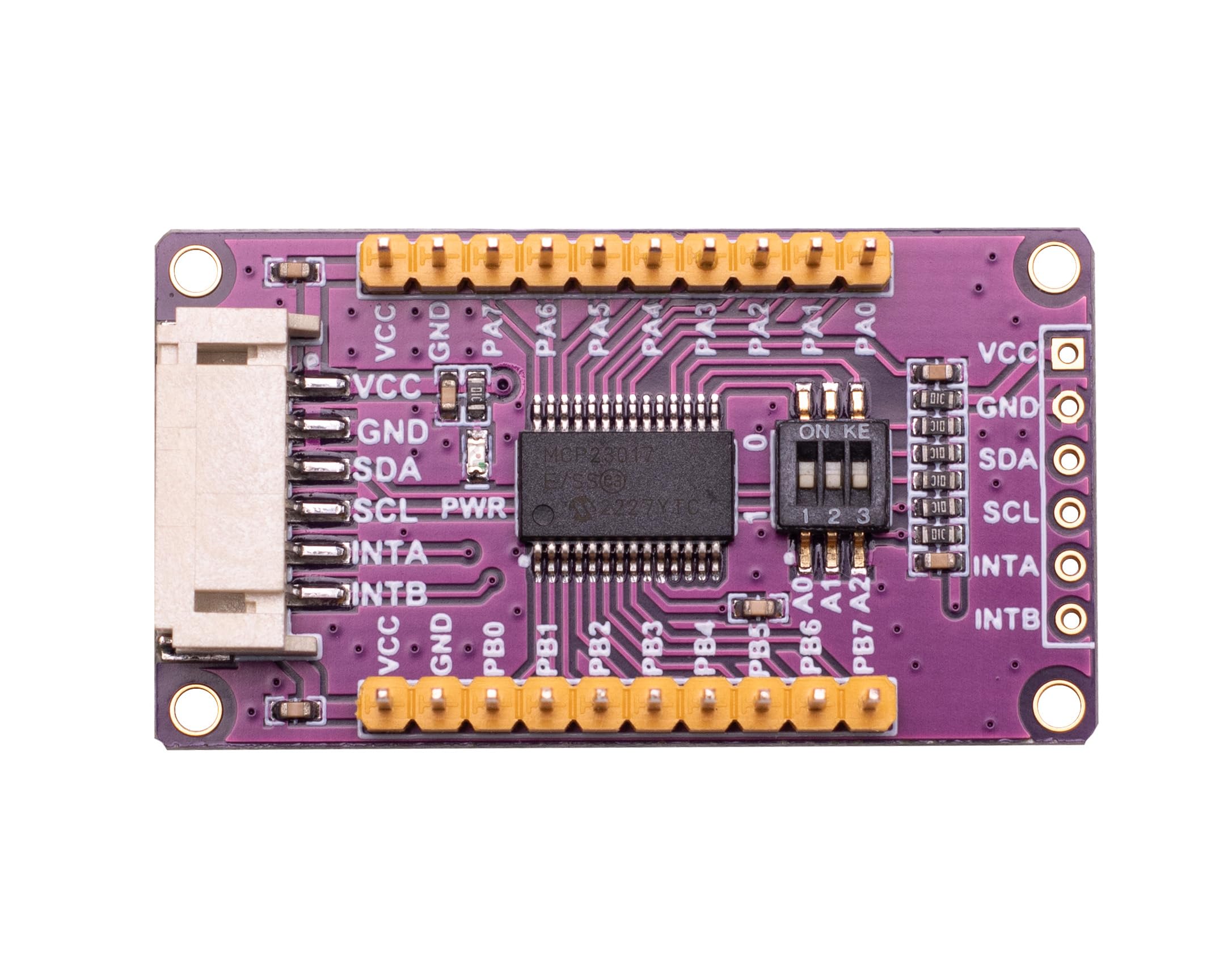
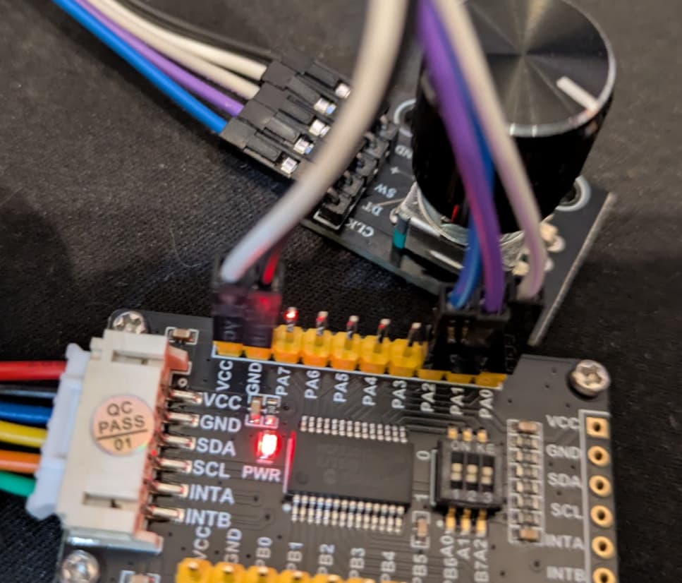
These are the integrated boards Wyleu it’s referring to. Thoroughly recommended, it can save you some soldering. Get one with dip switch to make changing the interface address easier. For connecting into the pi, there are some with a loom and connector, others have the pins on the board and some like the dfrobot (1st pic) have the both the connector and the pins already soldered so you can choose which way you want to connect.
There are many different tables/diagrams out there it just depends on your preference. I put some tape with ‘39 40’ on the ethernet port to remind me which way the pins count up/down.
For understanding how to connect the port expander mcp23017, I found this video helpful. Even though this is for the breadboard and discrete MCP chip, the same connection applies to the integrated boards shown above. I just watched it over few times until it finally started to click. Some electronics terms like pull up/pull down made no sense so I had to watch videos on that also.
I cannot recommend enough to draw simple layouts (like a square with 5 dashes) to represent the encoders and even the raspberry pi pins, then start numbering them according to what you are hooking up. It’s so easy to get lost in this process, you will save time by tracking what you are doing as you go along. Especially if you have to put it down and come back later to continue wiring!
@wyleu That is a great write up about encoders and wiring in the wiki! I used the zynthian development guide which really helped me start tinkering with drivers, cheers for the effort!
I don’t really understand what the 27 means. Anyway, at this point I would like to hook up 1 encoder. There’s PA0 to PA7 and PB0 to PB7. Are there some wiki instructions on how to set up encoders at this point. I tried reading your forum post but it’s a long thread and it’s hard to follow.
Do I actually need resistors?
Where do I connect the encoder’s clk, dt, & sw?
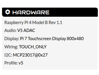
Looking at this section in the wiki: 5.2.1 MCP23017 I2C Address
I don’t really understand what this means. How does the terminal’s report show A0?:
ONce you have this then you can see that your MCP23017 is connected to Address A 0 . The default onfig. But you can change this if there is a conflict or your MCP23017 board has a different address set up. That’s what the A0, A1 & A2 pins are for.
Thanks again. All this stuff is very confusing to me.
No, these two “27” are unrelated I think. What you see in the i2cdetect call is probably your MCP23017 at address 0x27, which means you probably wired the 3 address connectors (named A0 to A2, sometimes D0 to D2 or similar) to 5V. Wiring all 3 to GND would result in the default address 0x20. I guess both would be fine as long as you setup it in the wiring section of the webconf. It is like binary numbers (000, 001, 010… results in 0x20, 0x21 …)
The default address is 0x20, you’ll achieve this by wiring A0, A1 and A2 to ground. These address pins work like a binary number. You’ll figure out how to address otherwise, but default 0x20 is GND, GND, GND, while your current config seems to be 5V, 5V, 5V.
The other 27 you’ll find in webconf when you state which pin you use for the INT-A and INT-B. If you’d use the same as me (Pin 36,37) that translate into wiringpi number 27 and 25 I think. You’ll find that in the dropdown menu.
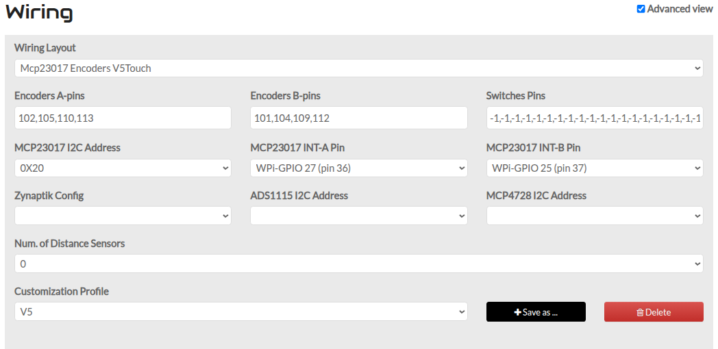
Tou connect them wherever you want on these PA0 - PB7 pinouts and state that in webconf wiring menu using numbers 100 .. 115 accordingly. SW is button press and the other two are decrement/increment, I don’t recall which is which. If you succeed but the encoder is reverted, just change these two.
Go through the above mentioned thread, I asked all your questions there and got suitable answers.
Ok, point taken. If you wire your first encoders CLK, DT, SW to PA0,1,2 and then state in webconf: address 0x27, Int-A: 100, Int-B: 101, Switch: 102 there are chances something works.
Of course GND to GND, and maybe (!) 5V to 5V (if your encoders have resistors included.
I don’t really know where those 100+ numbers come from for the “encoders A/B pins” I’m also guessing that based on my wiring I should be using pin 36 and pin 37?
I’m not getting any response from the encoder. Setting Encoders A/B/Switches to 100,101,102 doesn’t make a difference.
Just for fun I hooked up a second encoder to the other rails vcc, gnd, PB0, PB1, PB2 and this one works! It’s adjusting the volume and the push button switch goes to some strange menu.
It seems like the connections are working… Just gotta figure out what the encoder pins are for the PA0 to PA7 and PB0 to PB7
Yes, exactly. The twentyish “-1” represent your virtual touch buttons, followed by your 4 encoder switches. And yes, the PA0 to PB7 should be numbered fron 100 to 115. Seems to be conventional, 100+ numbers for expander pins, numbers below 100 for wiring directly to the PI (using the WiringPi numbers I guess).