Hey Folks,
I am building my own zynthian box from scratch and after some trouble (probably i picked up a broken touchscreen trying forever to get it working) i have the thing up and running on my hdmi computer screen and the Audio test functioning. However, at first i couldnt get the midi from the aio module working and tried midi over usb. i go into one of the usb ports with my m-audio code master-controller. the webconf tool shows that it pops up and i can log the midi messages in the webconf. however the zynth itself does not show any signs of playing a note or recieving anything (no green M or anything) when i hammer on the keys. Tried in single channel mode also. Is there a way of following up what the zynth does and how it is handling the incoming MIDI, e.g. through monitoring via ssh. I also logged some xruns on the way when using the zynthian.sh over ssh and, for that matter, quite many of them, which results in short overloads and blips and crashes. Also i need to test again with the AIO up and fixed.
The unit sometimes freezes when trying to select midi channels, as in the zynthian logo moves forever and i cannot do anything. Is there some way of adding a menu for selecting MIDI devices? I am comfy using this with midi channel assignment only but it would be fancy seeing if a MIDI device was identified and which port it uses, maybe even thinking about putting up a decent MIDI mapping with my CODE 61, because i would love to use the box as a standalone. However i am not quite sure on where to start such an implementation.
i got DIN socket midi circuit working now after some testing with my arduino and, as a sidenote here, i found that the scheme posted in this thread:
has the midi socket connections and LED’s in another way as when i follow the official WIKI scheme and numbering given there. On the latter, the connections on the MIDI IN/THRU/OUT are numbered according to the electrical wiring scheme uploaded in the Wiki and in the building process the numbers are given when connecting MIDI sockets and leds but it ends up being swapped compared to the former.
With the former scheme my midi circuitry works. I hope it is clear what i am asking here, i guess it needs some clarification on the scheme put up in the wiki. Hoever, along the way i was getting really confused after tripple checking everything for mistakes, so maybe its on my part as well.
Nonetheless, this is a really cool DYI project and i hope i can get it up and running. Help would be much appreciated!
Wiki instructions are OK for assembling the official kit, but probably you should “adapt” a little bit when building from scratch.
Anyway, could you be more detailed about what you think is badly explained in the wiki tutorial?
Please, be explicit about text fragments, include schemes with fixes, etc.
Also, take into account that lot of people have built zynthian boxes following these instructions …
I took that into account, which really made me struggle, i.e. i thought the problem is on my side.
I was only writing this since i am through with quadruple checking everything for mistakes and it appeared to be working only after swapping pins that i would never have swapped when following the wiki scheme.
When the midi sockets and leds are connected according to the wiki:
JST Red (1) => pin 4 of MIDI connector
JST Black (2) => pin 5 of MIDI connector
JST Yellow (3) => LED’s Cathode (LED’s black wire/short lead)
JST White (4) => LED’s Anode (LED’s red wire/long lead)
then my midi circuit will be on pins 1 and 2 and the led on 3 and 4.
This configuration didnt do the trick for me.
I did build a midi io circuit before for an arduino project and although i was using different resistances i couldnt see why this shouldnt do the trick.
However then i was checking this forum and found the one posted above: https://discourse.zynthian.org/uploads/default/original/1X/3e4f983aefb711c6394f7b966c5885e0b0735ce1.png
There it appears that the LED is connected to 1 and 2 and the midi socket takes 3 and 4.
Could be that the official PCB somehow does follow this wiring but then the scheme for rebuilding it without using the PCB is off. With the latter i could get my MIDI circuitry running.
Can you follow?
However, Midi over usb is still something i couldnt get and i dont know why.
webconf is finding the code61 and shows midi log. however zynmidirouter main does not appear to get any of this (is it supposed to?) and i cannot use the keyboard.
right channel double checked and tested with and without single channel mode.
Hope i could clarify and i am really curious why no one appeared to run across the wiring before?!
Yeah i kind of thought about doing this in the beginning too.
But i have got a decent amount of unused standard circuit boards and electrical components at home from a number of DYI projects, i sure had to get some, like the encoders and some diodes, but it amounted to around 15 euros for the aio and the rotary encoders. i even got the layout squeezed quite neatly and did a funny hack to use some rpi cables i already had. Also, if i am decisive on doing such a project i am usually not very patient and having to wait for a pcb that i can reproduce with everything i have at home is something i opt to bypass. all in all, the more DYI, the more i am proud of myself in the end and the more i am greatful for all the people in here to share their knowledge and opening up everything. So i know it is a bit bold to ask, after enduring some annoyance, while basically everything is fed to me in here beforehand. But i just wanted others to profit from my building experience, as in contributing something tiny along the way. Of course i could have followed the exact connections on the PCB layout and maybe then everything is clear (is it?!). But if the scheme is posted on the wiki, one is following it neatly and finds that there is room for improvement, it is not a bad idea to state so i guess?
Yes, I understand your point.
But in this case you are asking for help building a Diesel engine although everybody else is concentrating on building electric ones.
I don’t get this comparison. A PCB is just a layout giving the wiring and connections in a neat and accessible form. Obviously layouting myself will make the thing take up a little more space but apart from this there is not really a big difference to be honest. The soldering job is the same and i would call myself experienced enough to be able to pick and measure the right resistances etc… So this was really just about the wiring. I am only stating that if the wiring scheme put up in the wiki was used in creating the PCB, i cannot comprehend why it is working. If someone could clarify this for me it would be appreciated. If the wiring is somehow different in the PCB or the connections got assigned different numbers, than it would be just nice to state this somewhere for people who dont use the official PCB. That was the point i wanted to make. Since i actually thought about if it is possible to get two MIDI outs, for my specific set up, and hence wasn’t too keen on using the official version.
However the USB connection to my Masterkeyboard still persists to not work. I found a post on the github page and will follow what is stated there but i am a bit troubled still on clues what exactly fails.
Can i monitor the MIDI input and handling over SSH somehow?!
You are absolutely right. The pin numbering of MIDI/LED JST connectors was reversed in the Wiki’s tutorial indications, what probably caused your confusion. In the other hand, scheme and PCB are right
As most people are using the official kit, they probably used the “colour” indications, that are right, so the wrong pin numbering was not perceived until now.
I’ve fixed the documentation and i hope there is no more troubles with this in the future:

 and having to wait for a pcb that i can reproduce with everything i have at home is something i opt to bypass. all in all, the more DYI, the more i am proud of myself in the end and the more i am greatful for all the people in here to share their knowledge and opening up everything. So i know it is a bit bold to ask, after enduring some annoyance, while basically everything is fed to me in here beforehand. But i just wanted others to profit from my building experience, as in contributing something tiny along the way. Of course i could have followed the exact connections on the PCB layout and maybe then everything is clear (is it?!). But if the scheme is posted on the wiki, one is following it neatly and finds that there is room for improvement, it is not a bad idea to state so i guess?
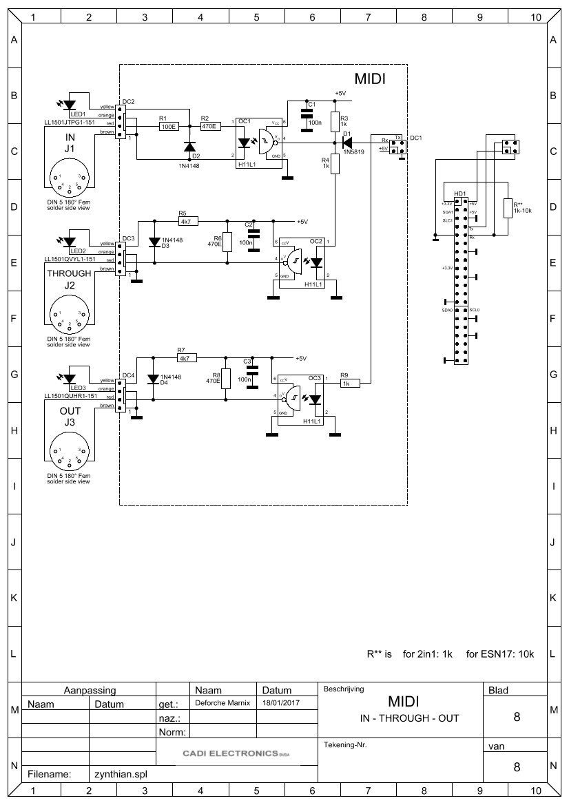