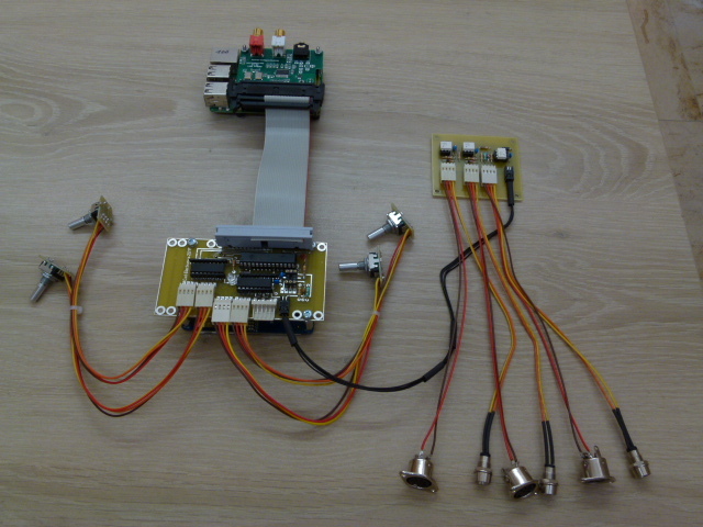
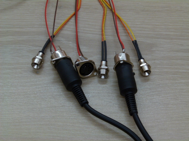
Always do a Visual check first
this can prevent much misery.
The test programs are meant to run on a standard Raspbian OS
as pi, in a therminal ( window )
they are written in python2 (zynthian uses python3).
The test is done at 38400 baud not on 31250 baud as in zynthian
31250 baud is not a selectable value on Debian-OS
the settings are complex to stand 31250 baud
the test can also be done at 38400 baud so we use for the convenience 38400 baud.
You can’t use a MIDI device as a test transmitter,you get only strange characters !
First we have to prepare our RPi to use the serial port
howto : look at MIDI on Hardware testing
If the RPi is ready
Open a terminal:
Run Tx.py
The RED led turns on everytime there is text sent.
Connect OUT to IN with a standard MIDI cable.
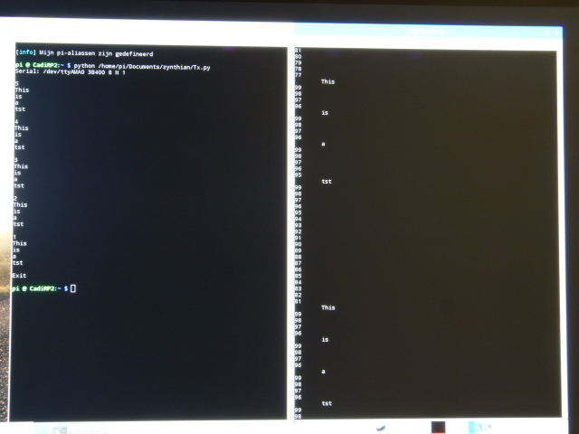
Open 2 terminals:
Run Rx.py in the first.
Run Tx.py again in the second
that gives the following:
Every time the RED led lights up, also the ORANGE (Through) and the GREEN (IN) lights up.
To test the THROUGH you need a second RPI that features a MIDI IN ( 2 in 1 for instance ).
Great work! Thanks for sharing! I’ve added your scheme and photos to the github HW repository.
What software are you using to generate these nice schemes?
Also, i’ve reorganized the HW repo, changing the directory structure and moving files from one place to other. Now the structure it’s more “per-module”, althought i’ve conserved some “global scope” directories.
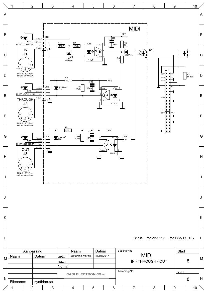
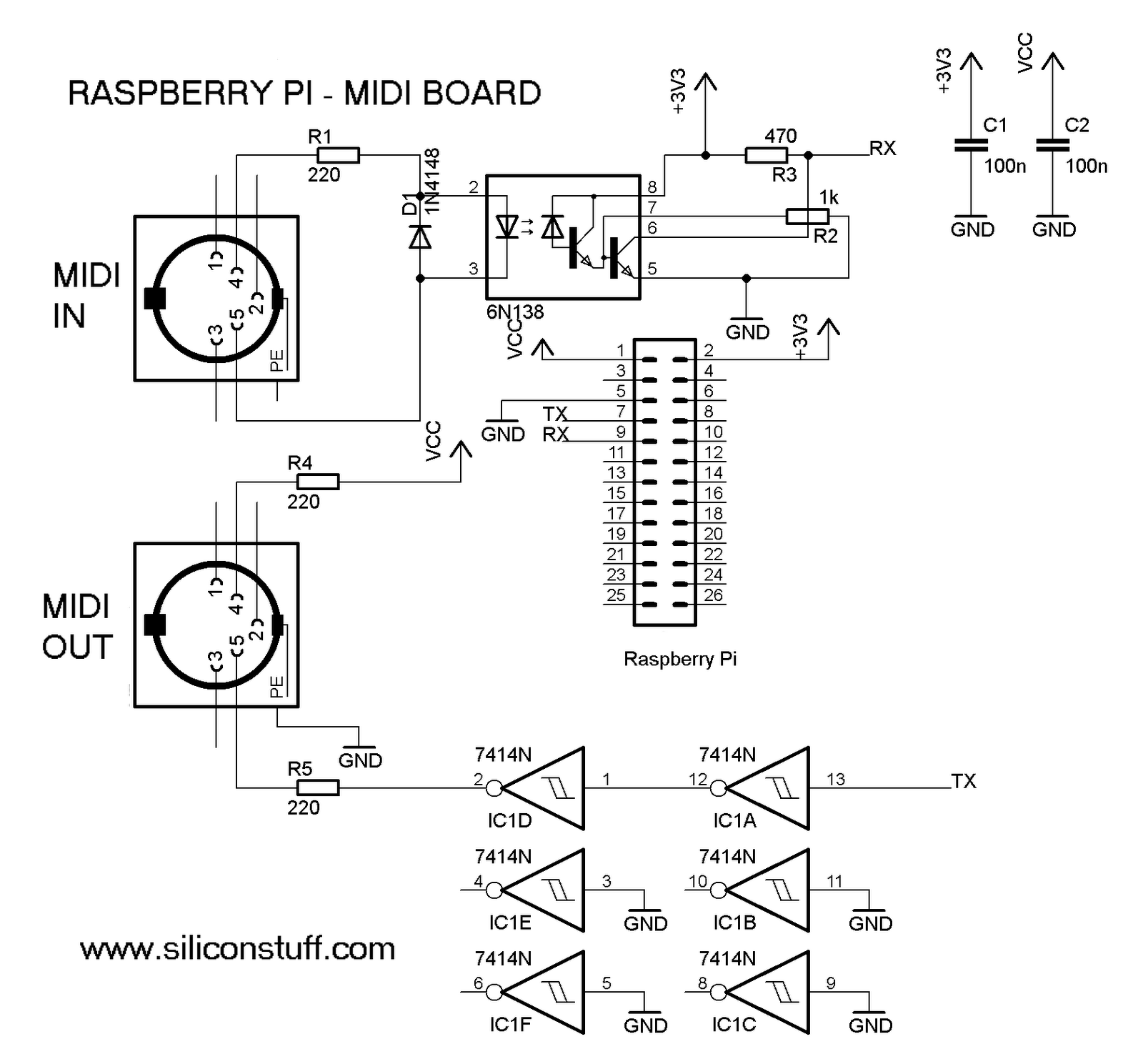
I’m having trouble sourcing H11L1 Optos in Asia, does anyone know if the 6N138 (or 6N137 or similar) would work in this circuit, as @Djeremaille ask above ? (sorry, my electronic knowledge is very basic !)
So, I think your suggestion is closer to midi standards.
But I like the OPs idea of trying to fully protect the RPI UART with 3 optocouplers, it’s nicely over-engineered.
I’m back in Europe soon, so can pick up whatever I want. I also found a supplier for electronic components locally here who have either optos ICs, so I’m all set.
I completely agree with you. The Imager’s circuit is really elegant, and the H11L1 is smaller than 6N138, so you will get a better protection and a slighty smaller circuit board. I will use it in the next official PCB