STOP NOW!!!
I replaced the SD card with the cloned one that I keep in reserve… MIDI WORKS too…
Now format the good SD and reinstall everything.
Thank you for your patience.
2 Likes
Work perfecly… Yessss!!!
2 Likes
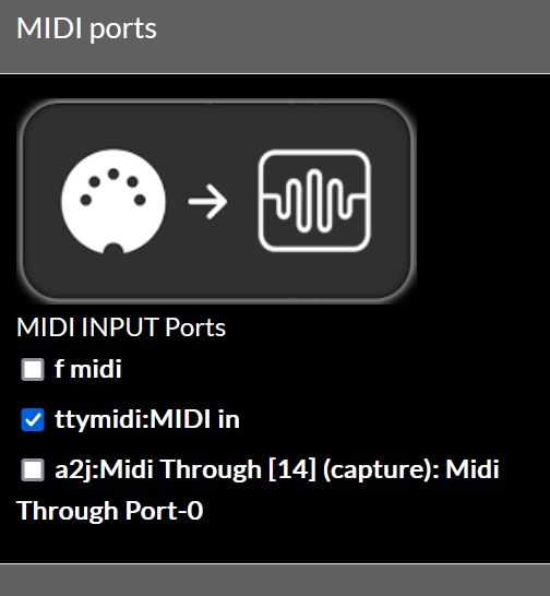
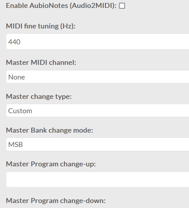
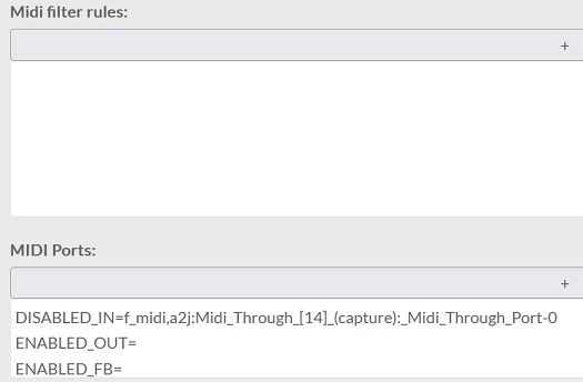
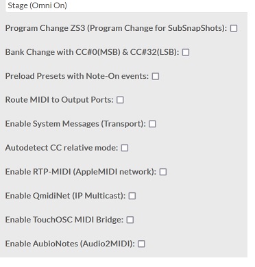
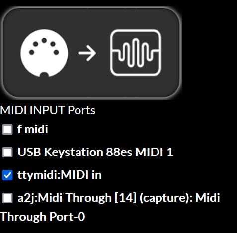
If someone inexperienced like me has this problem, they should set up the MIDI from webconf like this:
good… I reflashed the new SD I just received and the Midi doesn’t work anymore… same settings.
Could someone tell me if any setting is wrong?
Thank you
What MIDI doesn’t work? 5-pin DIN, network, USB? Input, output? Sequencer? Note on/off, CC? You need to be more descriptive to give us a clue what isn’t working for you.
Hi Riban…
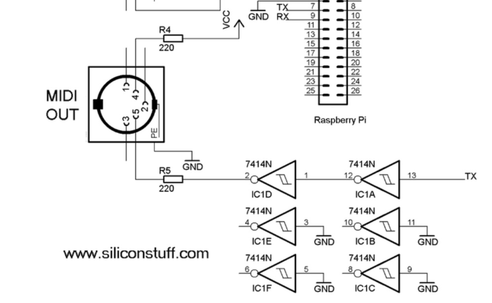
Beh, in this topic I’m talking about the MIDI shield mounted on a self-built Zynthian, therefore the midi in from a five-pole socket.
It no longer receives any signal … what makes me angry is that it worked for a few days and then stopped … either the midi shield died or some configuration changed … But I managed to make it work by doing attempts and therefore I’m not clear how the setting should be…
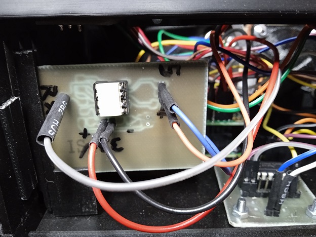
Found the defect… 6N138 was dead. I had one at the bottom of a drawer, replaced it and now everything works great. I still powered the shield at 5V because the 3.3V pin didn’t go to any track…
1 Like
Now everything works and so I recorded three tracks just for fun… One is Pianoteq8 Steinway jazz, one is Full Strings SFZ and the last one doesn’t come from Zynthian but from Kontakt and is Brass Ensemble by Native Instruments… ![]()
4 Likes
Built the midi shield for the Zynthian… Now it works perfectly and at 3.3V.
A question for Dr. Riban if you feel like it … I have not and have not mounted the countervoltage diode on the Optoisolator LED … is it serious?
Thank you
Hi @Lanfranco !
This diode is important because the serial MIDI signal uses a current loop (there were good reasons to do it like this when MIDI was first developed), so the diode protects from overvoltage the optocoupler’s input when the current changes its direction, what could happen quite easily. In fact, it’s the most probable cause of dead for your optocoupler. I strongly advise you to add this diode. Alternately, you could buy a good amount of optocouplers and replace it each time it dies ![]()
Regards,
2 Likes
![]()
![]()
![]()
![]() Thank you very much for the information. I see if I have some smd diode to insert. Is the value critical? Thank you
Thank you very much for the information. I see if I have some smd diode to insert. Is the value critical? Thank you
I knew this thing because I have built many things with relays and these components also need the countervoltage diode even if for other reasons.
In the shield that I used until yesterday, there is a countervoltage diode… But that shield worked at 5V, which is why I wanted to build one myself.
P.S.
Meanwhile I soldered a 1N5711… the only one I had… otherwise I have a dozen 1N5820s that are as big as my finger… I used them for the power supply of the tube transceiver… ![]()
![]()
![]()
![]()
![]()
![]()
1 Like
The reason for this kind of diodes is always the same: allow current to circulate, avoiding overvoltage.
It should work ![]()
Regards,
1 Like
The diode across the coil of a relay is to collapse the large voltage spikes that are created by the induction of the coil. When it energises there is a complex LCR interaction which creates large potential difference (back emf) that can (and will) damage sensitive components such as transistors.
The diode across an optoisolator is to protect against reverse polarity voltage. Applying 5V (or 3.3V in this case) the wrong way will fry your poor opto which can certainly block reverse voltage (that is the point of a diode) but only up to a point. To protect against overvolatage you need a zener diode which will pass current in the reverse direction when a threshold is reached. (This goes after the current limiting resistor to avoid a dead short and the zener frying.)
The current loop is still a very much used method of delivering signal over relatively long distances (meters). It is easier to reliably detect signals indicated by current fluctuations than it is to detect voltage changes. The current will be the same through the whole loop (at the send and receive points) but the voltage differs depending on the inductance of the path (e.g. interconnects). So a transmitter and drive the circuit at 20mA and the receiver can detect a 20mA signal. The driver adjusts the potential (voltage) to ensure the signal remains within the specified tollerance of 20mA. The detector in our case (MIDI) is an optoisolator that is a current driven and dependant device (LED) that also provides electrical isolation which is very useful for avoiding audio issues like ground loop hum.
1 Like
An encyclopedia…thank you Jofemodo and Riban for your sharing of knowledge.
From the top of my infinite ignorance about MIDI (I’m getting to know MIDI now with the Zynthian, until now I’ve always recorded everything in audio) I’d like to ask you yet another info… Connecting the keyboard via USB to the computer and recording a part in MIDI using the sounds of the Zynthian (which is connected via MIDI to the sound card) I notice an obvious latency. If I modify my MIDI shield and create a MIDI OUT… if I connect the keyboard directly to the Zynthian via usb, can I send the midi messages to the computer thus halving the distance they have to go? I apologize for the lack of knowledge and thank you for any clarification.
You can (but shouldn’t) create a Y cable 1midiIN / 2midiOUT and check.
But put this cable to the trash after, it’s not the good way to split the signal.
Or disconnect every USB device on the computer except the keyboard and see if it’s better.
Thanks Wapata,
I built the MIDI interface, so I can easily rebuild it with 2 optoisolators in order to have separate In and OUT. What I don’t know is if I can connect the keyboard to the Zynthian via usb so that the Zynthian sends the “notes” to the DAW via the MIDI OUT. In this way the journey would be shorter.
Yes you can: Zynthian Features - ZynthianWiki
- MIDI filter/router: All input MIDI messages are routed thru the MIDI router/filter (zyncoder), that can be configured using simple rules from the webconf tool. The output MIDI stream is sent to synth engines and to the desired MIDI outs. No extra latency is added. Everything is done in the same jack processing frame.
2 Likes
Yessss! Many thanks.