it appears this dude knew much more than I know what im doing, as others pointed him in the direction, and he took care of business… I think I may need a bit more hand holding, but Im esentially using the same basis as that dude. I got a PI4, a pisound, a mcp23017, and some ky040 encoders (read that these have a resistor in there)
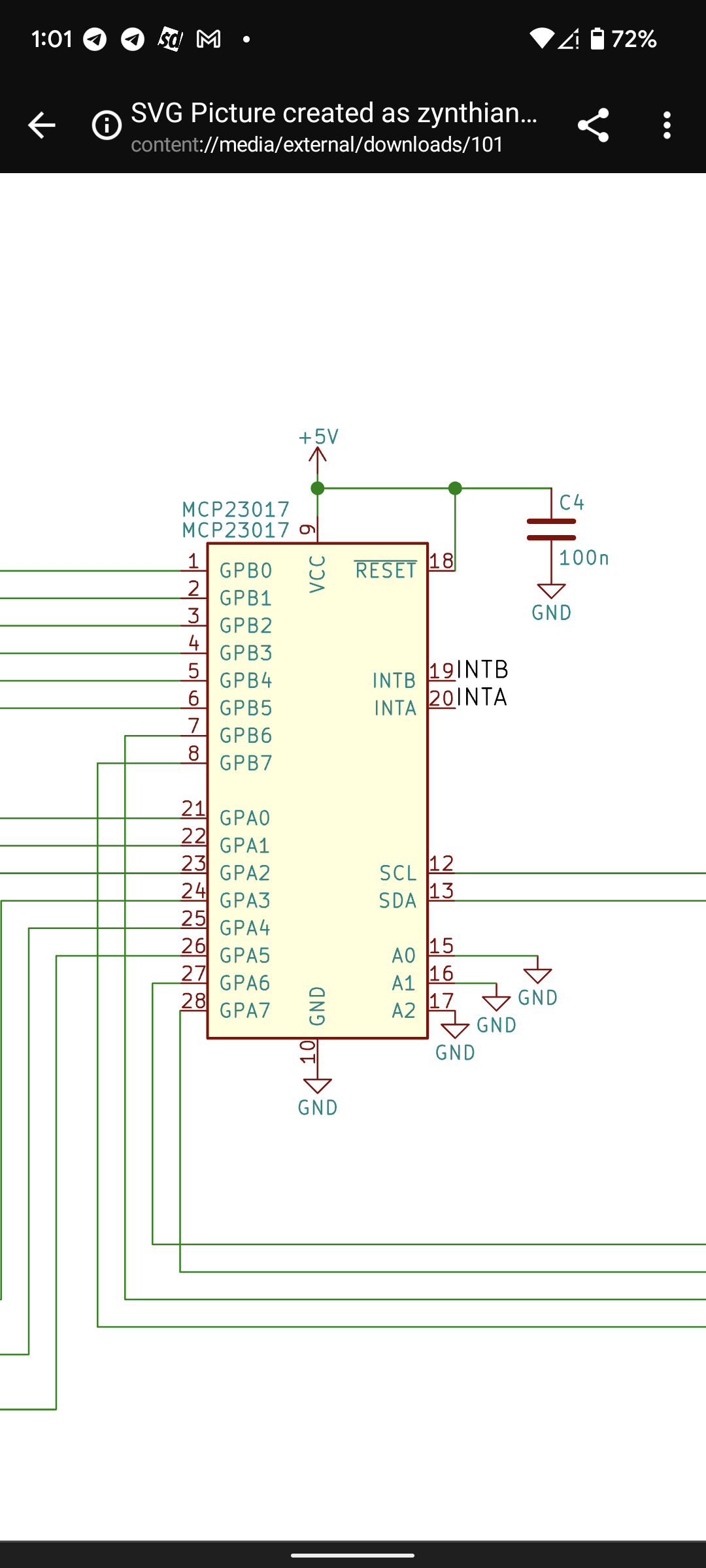
i know ill jump in the webconf once i make the connections, but i looked over the allinone schematic and some of it makes sense, and some doesnt since this is my first foot into rolling my own build. when looking at that mcp diagram, what is inta intb? all thes encoders have a ground, can it all share the same ground pin? pin 7 8 27 28 go to sw1 (what is sw1 and sw-1)? vcc and reset goes to a c4 (whats a c4 other than an explosive? goin to a 100n (i guess its a resistor?)
So i can probably take a picture of this lot of PI stuff I bought, but i dont know what half of it would be useful. I do have a small 3.5 lcd, and a 7inch waveshare, and 7inch official pi display, but doesnt these displays also have to connect to the MCP?
since im an idiot, I will surely make a thorough post if I ever get this all working. this way the next idiot can do it with less assistance than i, and of course a brief sound and many pictures once its all done.
So I’m trying to find that allinone schematic, and I think I’ve found one from 2019… I’m afraid if I start soldering, there is probably a more up to date schematic for the mcp23017.
Looking through a box of pi stuff I bought on eBay, I’ve located two of the mcp23017 that I lifted from the breadboard.
Since I have the ky040 encoders with some resistor on there, what should I do? The allinone has scl and sda, what are those? Also what is the inta and intb? Also is that vcc and reset going right to the 5v header on the pi? It looks like there is also a lead from both of them going to a C4 and 100n to the ground? Can someone link me where I buy some c4 and 100n?
Also can you give me a quick rundown what is the c4 and 100n? And why are the ky040 resistors a problem with the schematic. I plan on seeing this out, I just don’t want to fry anything
I’m looking through that GitHub page you linked… Those kcad and Gerber files are just for 3d prints right? I’m trying to learn to walk before I run; I don’t care about the 3d case until I know everything is working. Looking in the allinone link expands to like 30 items, and not familiar with any of those file extensions, and the pdf and jpg files are just a picture of components like the hifiberry and stuff with just an arbitrary line connecting them. I don’t see any files named mcp23017 to indicate what the resistors are. Maybe I’m just not understanding what I’m trying to look for… As I mentioned, I’m just looking for something thorough about components, wiring , the resistors, why people have or don’t have it… I have a pisound , and the post that sounds helpful about the pisound , the dude knew what he was looking for and didn’t really explain much .
Im not sure I get where something I need is hiding… I expand the code on GitHub but I’m lost. I spent many hours on the wiki, and short of what I need to find. I do know once I connect everything, I may need to reconfigure the pins on the webconf, but that is it.
It sounds like you are a novice with electronics. You may wish to consider a simpler project to start your engineering adventure. My foray into this world started with a lamp and a battery and progressed rapidly through resistors, transistors, capacitors, ICs, inductors, etc. Within weeks I was building complex circuits and within months designing my own. That was more than 40 years ago and I have probably forgotten much of what I have learned but you do need to start at the beginning.
If you want to experience Zynthian in all of its glory with minimal engineering experience then the kit of parts is the best place to begin. It does not involve any design or soldering, just plug it together. If the kit is unavailable (maybe due to world shortage of components) then you may wish to build a very simple Zynthian without the extra electronic hardware, e.g. without encoders then in parallel learn the basics of electronics. I am sure you will be able to gain sufficient understanding pretty quickly of circuit diagrams and how that relates to putting a more complex Zynthian together.
Zynthian kits are aimed at the technically minded user who does not have engineering skills. DIY Zynthian (not from a kit) is within the realms of the more experienced electronic hobbyist.
Good luck. A little perseverance will get you a long way if you follow the right path (or not too many dead ends!).
so im back. i figured i was getting frustrated and needed to walk away. so using my generous 2mbps internet connection, i downloaded kicad. Not really noticing anything that I hadn’t seen in a picture floating around here.
I look at that allinone thing and because it’s made on the assumption you are using actual zynthian printed hardware, some stuff ain’t adding up. First,
I, again, am referring to a pile of parts I have, no zynthian screen boards controller etc. So I have a few mcp23017 laying around and it has 14 pins on each side=28 pins total. Since 26 pins are used in the allinone, I’d assume 2 are just unused? Another observation/question, if I’m using these ky040 encoders with 5 pins… I read stuff from back in 2018 that you don’t use the + pin, but I see stuff in the forum from 2020 to use the + pin. Just a question because the reason discussion boards are shit, are the same reasons they are nice… They take many hours to research something and you still may never come to a conclusion on a topic.
Since every pin is assigned in the webconf in software, nothing really matters what you connect right? I ask because you just see on encoders on the allinone are just lines and not really labeled , other than the ground.
I think you would really benefit from slowing down and building some basic circuits from schematics first.
There’s a lot of fundamental stuff to practice before jumping into a full diy synth.
Start by building some basic 23017 circuits in breadboard, they will get you acquainted with wiring and powering circuits. I suggest starting with arduino as they cheap and easy to replace as you will kill more than one, Youre very likely to fry your Pi if you proceed without knowing how to read and connect power from schematics.
I really appreciate the whole information thing. I have read through it and it makes some stuff clear. I don’t think im any more stupid then most people who successfully got their build going without using the whole ready to go zynthian pack.
So I’ve soldered and successfully installed modchips on a ps2 and a old ps1… I don’t know how they work, but I got it working by just following directions and I’m ok with the magic of spoofing memory addresses and overwriting this and that swapping going on in the background. I guess the point I’m making is I’m ok with not knowing the ins and outs of how the mcp23017 interface works.
I am asking what resistors and other materials I need to hook this thing up and get it working. I got male and female connectors and all kinds of wire. I got solder and soldering iron. I got the mcp23017 chips, I got many encoders and just looking for info to complete this project and be respectful to it’s inner workings without actually knowing every bit of computer science behind it.
So what else must I purchase to complete this build. I’m not using a display through the gpio. Nobody said or mentioned what the c4 in the allinone is off the 5v and reset. Or the what the 100n is.
C4 is a capacitor. ‘C’ is the common definition of a capacitor in a circuit and ‘4’ indicates it is the fourth capacitor or component (depending on how the author numbers their components). 100n is the value of the capacitor. 100 nanoFarads. Farad is the SI unit for capacitance. One Farad is very big so capacitors have values scaled down using orders of 10 divisors. ‘n’ stands for ‘nano’ and means 0.000000001.
This is good stuff. I see how all the info you dished out to me actually brings some light into what I’m looking at. Thank you much… it’s let’s me know the stuff I have on hand is no good. So that capicator is always nessecary on the reset pin on the mcp? Also if I got that 100n capacitor, is a 50v ok or should I look for a 10v or such.
Also I have a display hooked up. Kept messing with it and eventually got a zynthian error message with video. Couldn’t do anything so I reflashed. I got a paper with the display, jrp7007 “7 inch HDMI display”. Had this. Went in the web config, to display, tried generic HDMI, nothing. Restarted , went in there added all that stuff under advanced settings. Nothing. Tried both putting 1024 in width and 600 height. And leaving it empty. Any suggestions? Couldn’t find much pertinent help.
A capacitor is like an electrical bucket. Farads describes how big the bucket is. It has an interesting property in that it will fill up with electrons till it is full and then simply sits there full of charge. So if one is placed across a Power supply line it will smooth out the voltage particularly sudden spikes and such like which is what it’s doing in this circuit. A bit like a shock absorber. You will often see them nar chips on boards to smooth out the supply for the chip, especially in digital circuits.
The voltage quoted simply is the maximum the maximum voltage that the particular capacitor can take without failing so as long as it’s bigger than the maximum voltage in the circuit then you should be ok.
Just as a note bigger capacitors, those involving microfarads are constructed of materials that rely on the polarity of the electricity not changing, or to put it another way they fail ( sometimes impressively) if they are connected the wrong way round on a circuit. These have a plus and a minus marked on the bodies and it will also be shown on the circuit . But this capacitor is an ordinary cap and doesn’t have such worries …
As helpful as we all are to each other I really think this is not the forum to teach entry level electronics. There are many resources on the Internet and in the real world to obtain this knowledge. Taking time to explain the basics of a hobby interest so that someone can get to a sufficient level of knowledge and experience to start using a project is not really within the scope of any project. Please read and listen to the well intended advice and search for a suitable resource to educate in the art of electronics. (BTW, The Art of Electronics was our bible.)
I worry that we have limited resources here to support people trying to build, use and enhance the Zynthian and those resources may be unduly diluted by providing training to reach the minimum entry level for this project.
I am sure we all look forward to seeing a more informed and still eager to learn member of the community after they have taken the time to self educate a little more.
I appreciate the help. All i can say is my successes will undoubtedly help someone in the future. its just unfortunate with all the tutorials, people knowledgeable enough to pull off their project, dont really go super in depth. I will probably say youre throwing a patronizing comment my way, but i know you help many people in this forum, and hopefully you , riban, will be around to see me stick this out until completion.
All help is appreciated… and hopefully someone can help me get that hdmi display going. so i ask, is the config.txt written by way of the webconf? that jrp7007 monitor works fine in patchboxOS, but cant get a pulse inside zynthian. i tried throwing this in the display config in the zynthian webconf. i will throw this in the config.txt and see if there is any luck.
With the greatest respect, if you want to lay out your own circuits for a diy synth, you’re going to have to learn how to read and lay out circuits. This means spending time building basic circuits from scratch and troubleshooting.
Learning some electronics theory is unavoidable.
If you want to Implement a 23017 from a schematic, you’ll have to spend some time building basic circuits with it to understand how to power it and address it. If you don’t want to learn this stuff, buy a kit where it all snaps together. I don’t even begin to understand how these chips actually work, but I now know how to read a data sheet and implement them.
I went from nothing to building my own fully diy zynth including my own control boards, based on the link I posted.
But it took over a year of tinkering and lots of diversions where I had to stop and build other circuits not part of the zynth, just to learn how to implement them.
Search the forum for other posts with hdmi out and tinker with the code and google until it works. This is how most of us here are working with DIY.
Ive never used hdmi out so have nothing to offer, but happy to help with MCP implementation etc if you get stuck.