As jose suggested I will ask my question here in the forum.
Last days I build my zynthian but something is wrong.
When I connect the all-in-one module the respberry does not start.
When I start without connecting the module the pi starts and I can see the start script on my 5 inch waveshare screen and zyntian works.
I can control zynthian with a usb mouse. Not with touch screen.
When i have connected the all-in-one module i have no access to the pi from my pc.
The pi is not listed in my network!
By the way i use the android app “fing” to find the ip for the pi. Is very easy!
What I have done until now:
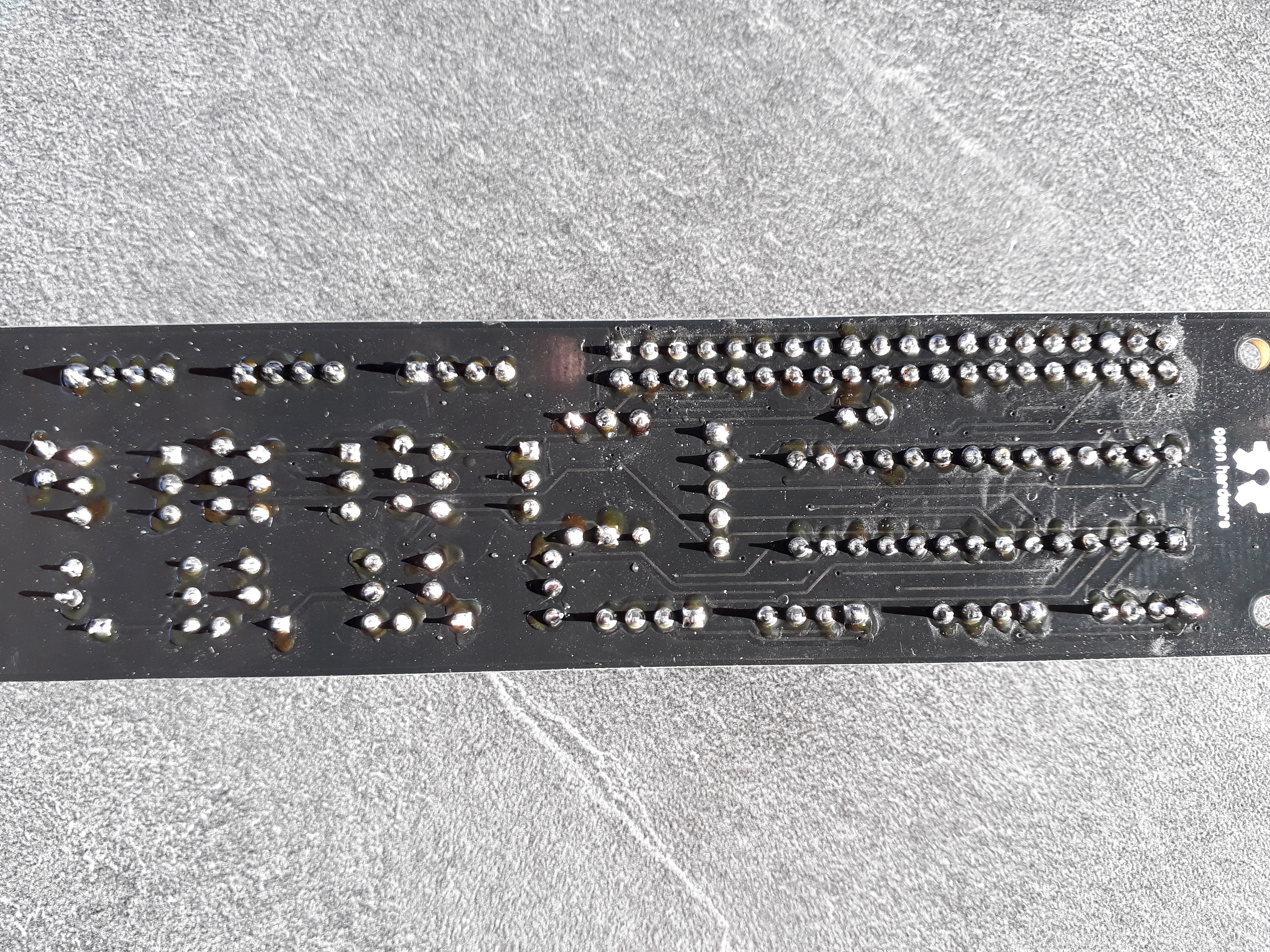
I have checked the soldering – for me its ok.
I have checked the components on the pcb – for me its ok.
I used an other ribbon bus cable from my old pc – same problem
The pwr led is red and the act led is off.
The d1 led on the hifiberry also is off.
When i disconnect the all-in-one module the pwr led is red and the act led is flashing in green. After a few seconds thee d1 led on the hifiberry is red.
AFAIK there is just one way to cripple the boot process from the GPIOs, and it requires burning the GPIO Boot Mode OTP fuse.
Once done (IT CAN’T BE UNDONE!) then you must use GPIOs from 22 to 26 to select the boot device (SD1, SD2, NAND, SPI, USB mass storage)
But it’s obviously not your case…
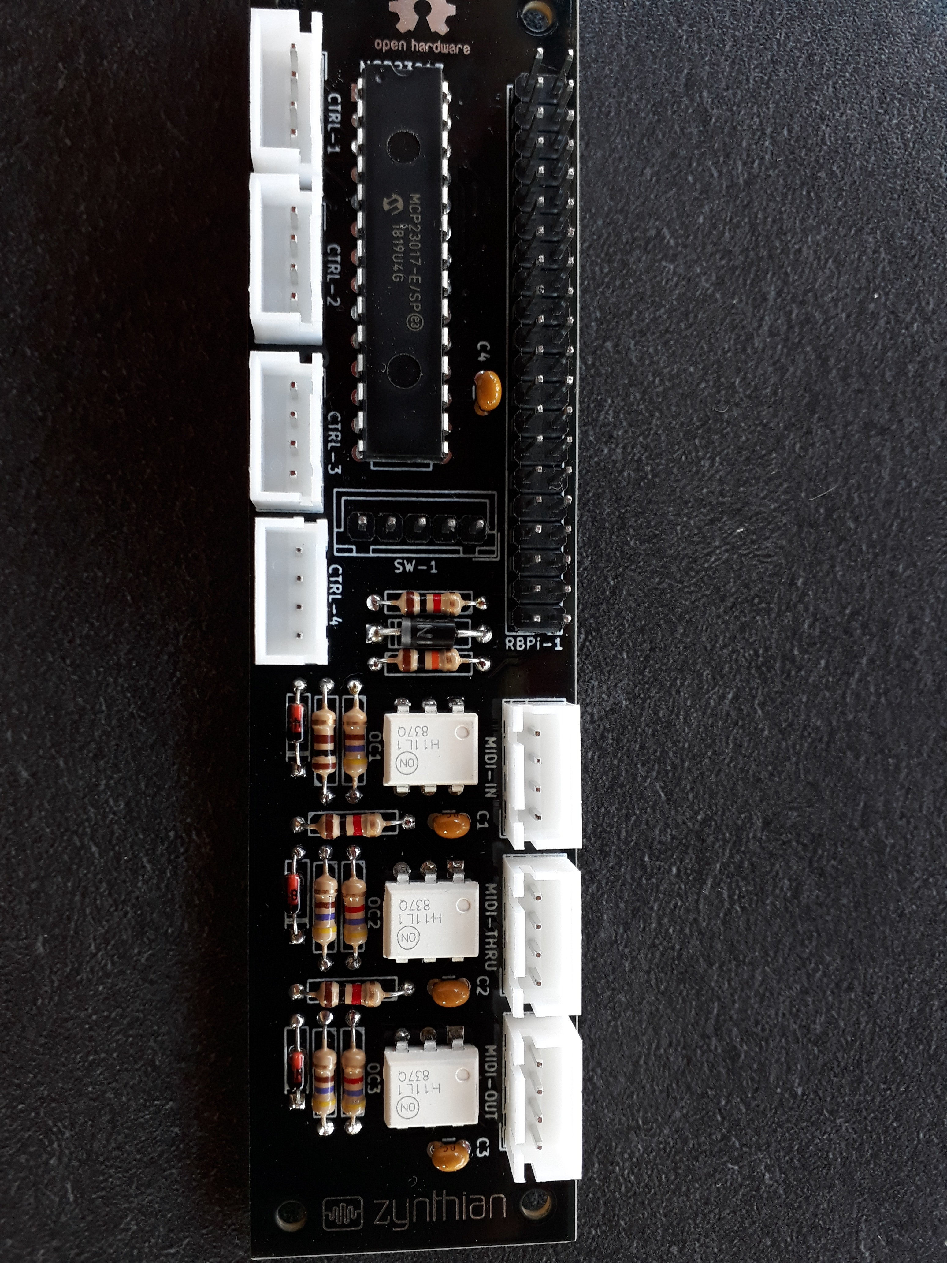
As @jofemodo said, please upload some picture of both sides of all in one. BIG and IN FOCUS
EDIT: There is another way to freeze the boot: you’re overloading the 3v3 and the SD (better, the whole SoC) doesn’t get enough power do do its job.
I don’t believe it’s a main power rail problem. The rPI red LED blinks if main voltage is less than 4.7V. and above that voltage, the rPI should boot anyway (maybe with the undervoltage indicator on screen)
You should measure the 3v3 level on the GPIOs connector. That voltage is not monitored by red LED (it was, in the first rPI hardware version)
I measured the 3v3 pins (1 and 17) to the GND pins. At every combination i get 3.298 to 3.3 V.
I think they are ok.
I also checked if there is no short- circuit on the all-in-one 40-pin-double-row male connector. The only short-circuit is between pin 2 and pin 4. But i think thats ok.
Now i will test what @mheidt thinks. I will order a new one MCP23017 with socket and will change it.
After that i will give report.
Thanks for now!
Desolder just the chip it from the board and try again. If the culprit is the MCP, the system will boot without it. But I bet my two cents against that, 'cause (if I read the right schematic) the expander just use the 5V and the I2C port, and this should not interphere with the boot process.
And as @mheidt said, always use sockets.
Do you live in Germany? I am not sure, but I think I have one at home and can send it to you. Problem: I am back from holidays at Aug, 1st - so cannot search and send before.
Is here any missunderstanding? I have 5 MCP at home and tested the all-in-one module with 3 different of them. Nothing works! When i take the MCP away the raspberry runs! It is strage.
Is it a logic or PS start up failure when the chip is present?
i.e. do you see 5V and 3.3V respectively with respect to a ground (6,9,14,20 etc) on pins 1(3.3v) ,2 and 4 (5V)? IS there a led on the Pi lit when the chip goes in?
If looks like a PSU problem top right there and start looking hard at the connections on the board. Logic into a PS rail via a short can find a route thro’ a chip.
If not it’s lying to the bus in some way or holding down a signal that should be floating to +V.
Again careful investigation round the chip with a Multimeter can often reveal connections that only reveal themselves as a hair of solder on close examination.
Keep at it, electrons don’t bare grudges either…
Mind you if you have 5 MCP23017 at home you’ve probably walked this way before …
Do you have anything that does work that needs a 23017 and can therefore check that the chips are still conscious after their encounter with the board?
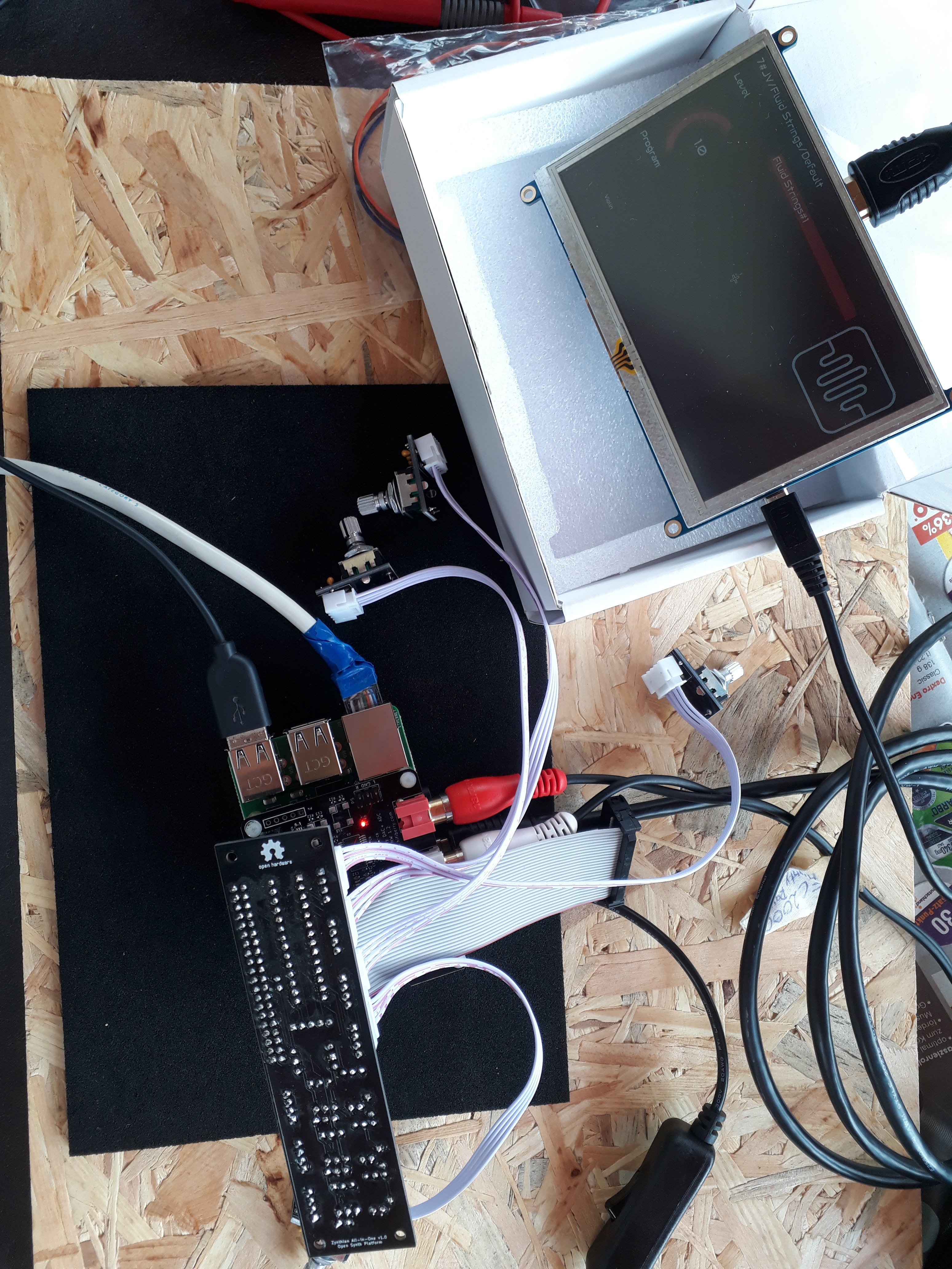
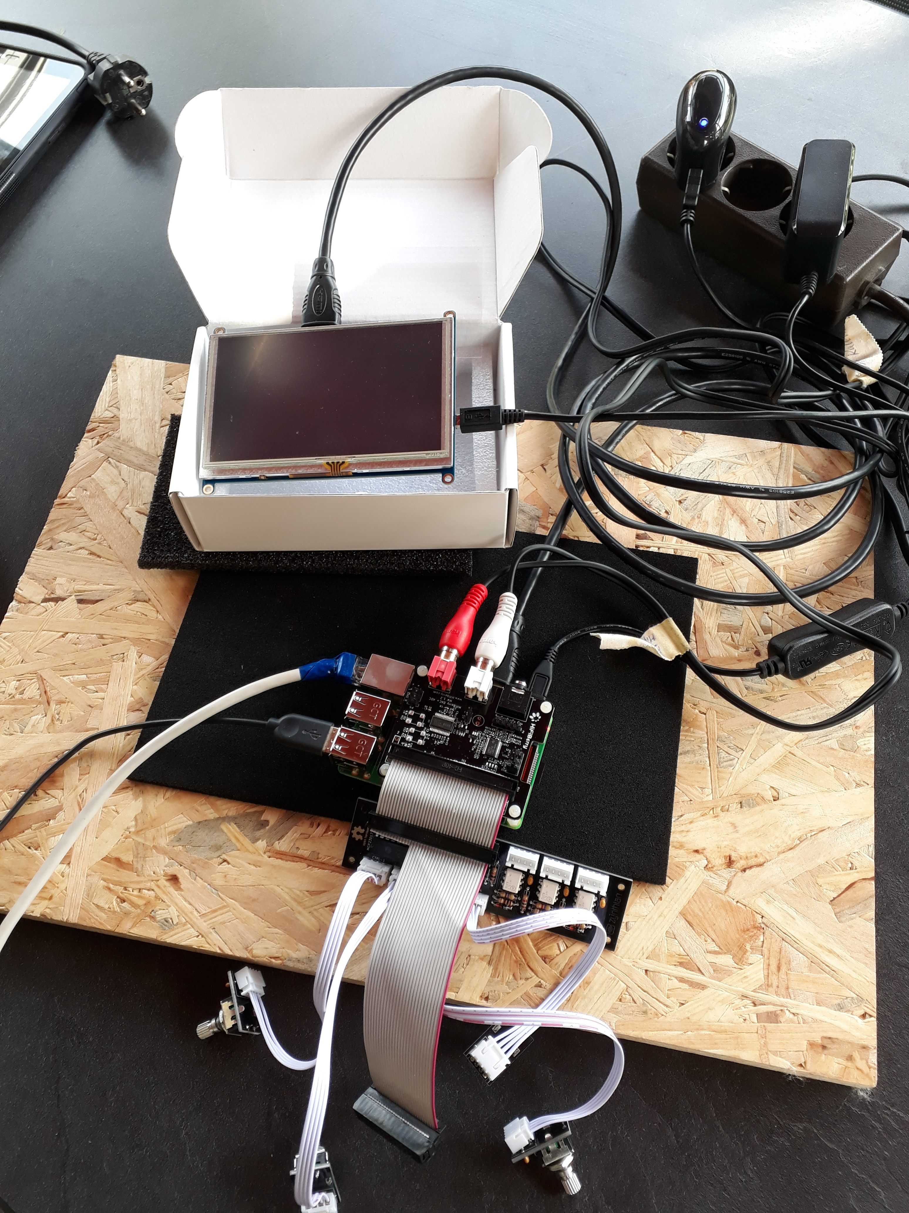
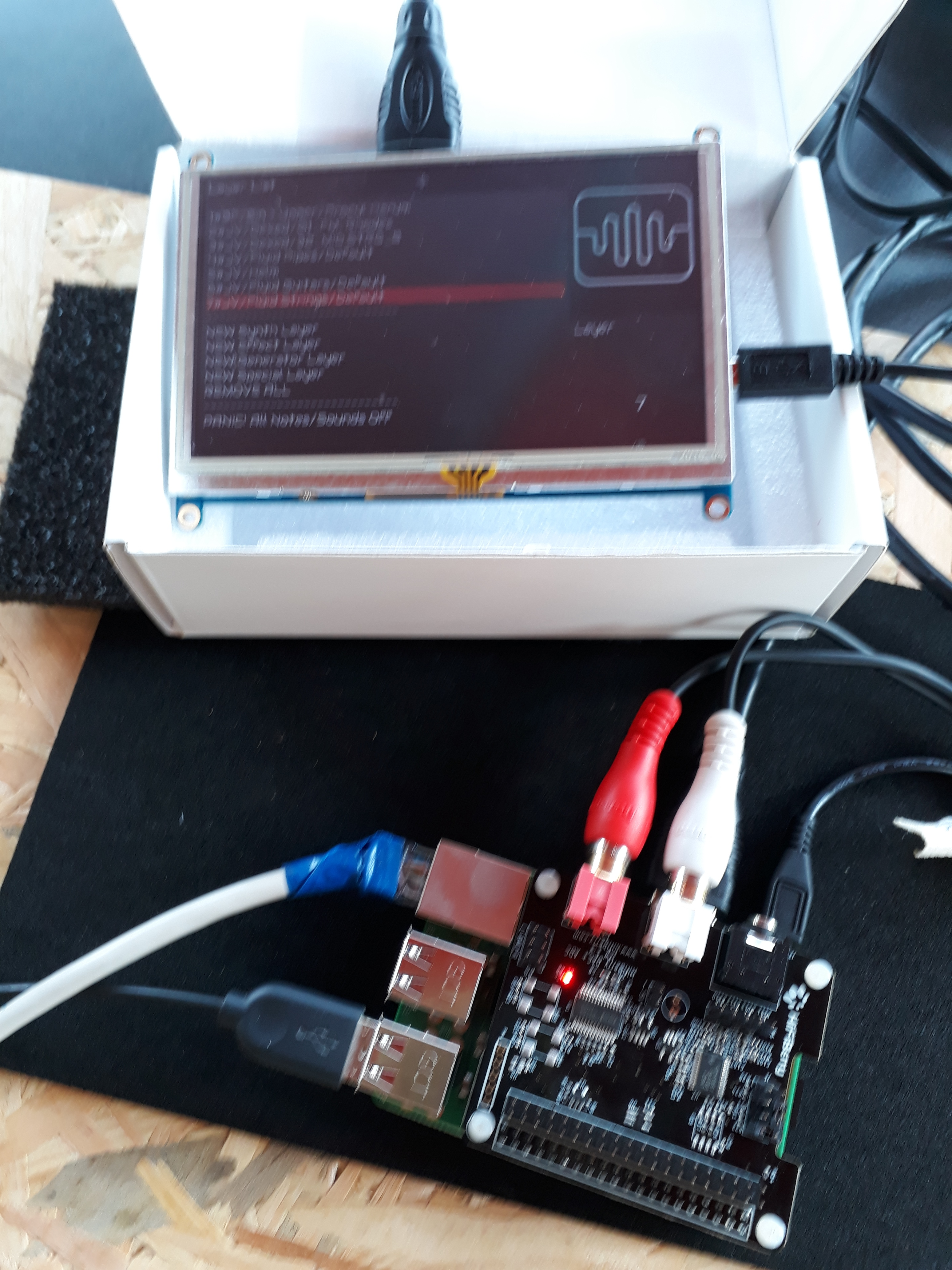
New situation! Today as i tried to do some mesurements like @wyleu suggested i turned back the all-in-one like you can see in the picture and than the pi starts! I connected to the zynthian with ip and i can change the settings so that i can work with the rotery switches.
When i turneded back the cable of the bus and tried again starting the pi does not start.
I tried it more than one times with bending the cable of the bus. Sometimes it runs, sometimes not.
I also tried a old bus cable from my old PC. Here also i have bend the cable and sometimes ist runs and sometimes not.
But I can’t exactly recreate the situation. It is trial and error!
I hope you can give me more tips what I can still check.
I’m busy hating 40 pin ribbon connectors at the moment so that might be part of the issue. Isolate mechanical components as much as you can and then move other bits to see if you can ‘reliably’ re create the fault.

 …
…