Thanks Riban
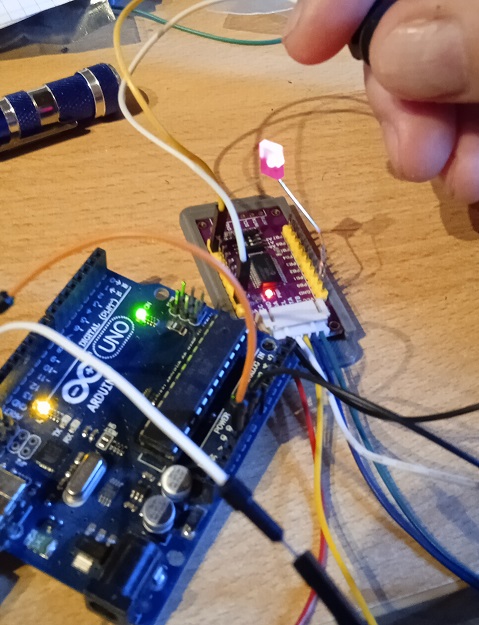
The INT1-4 are the buttons of the encoders…
The board is powered at 3.3V
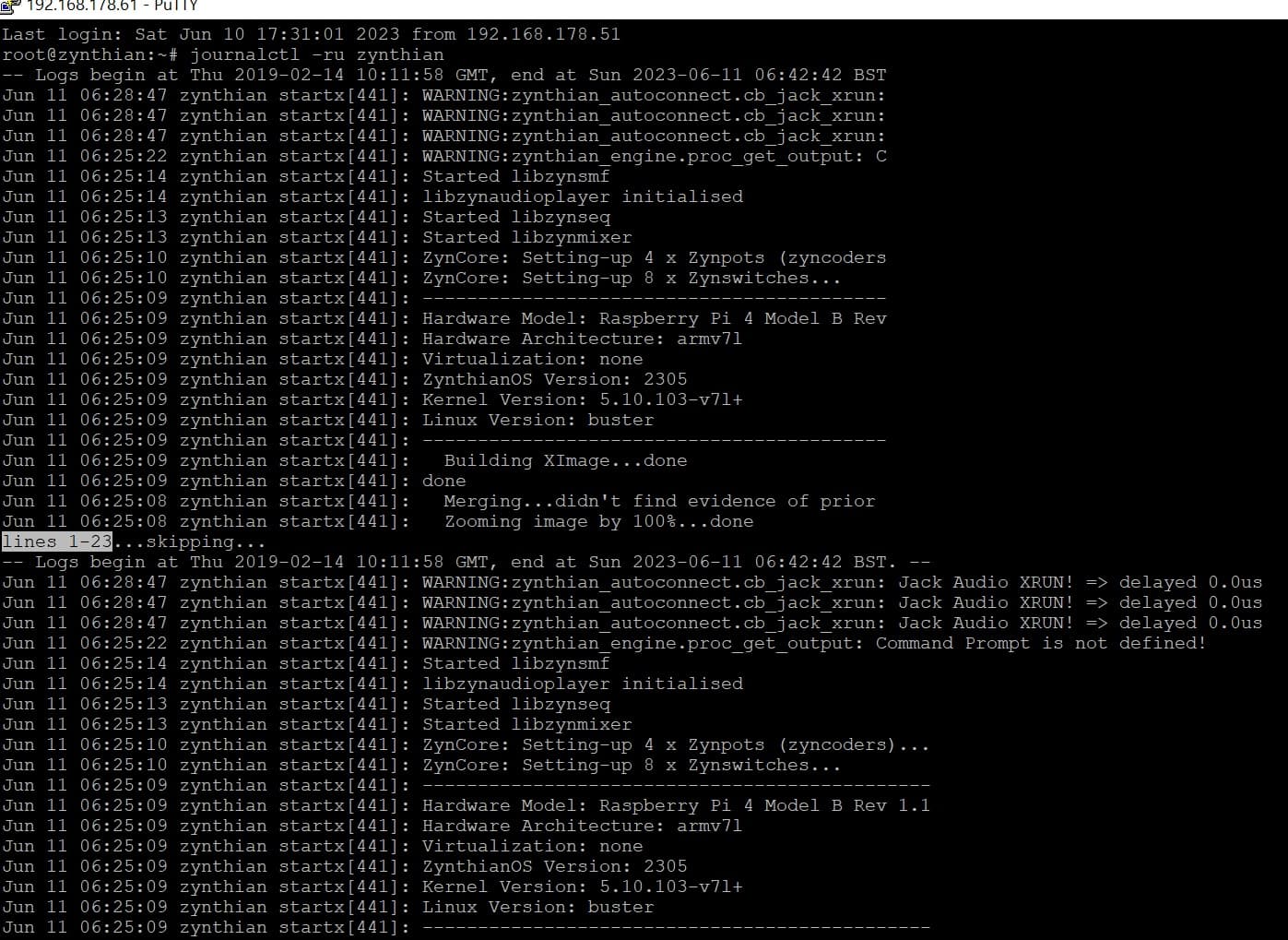
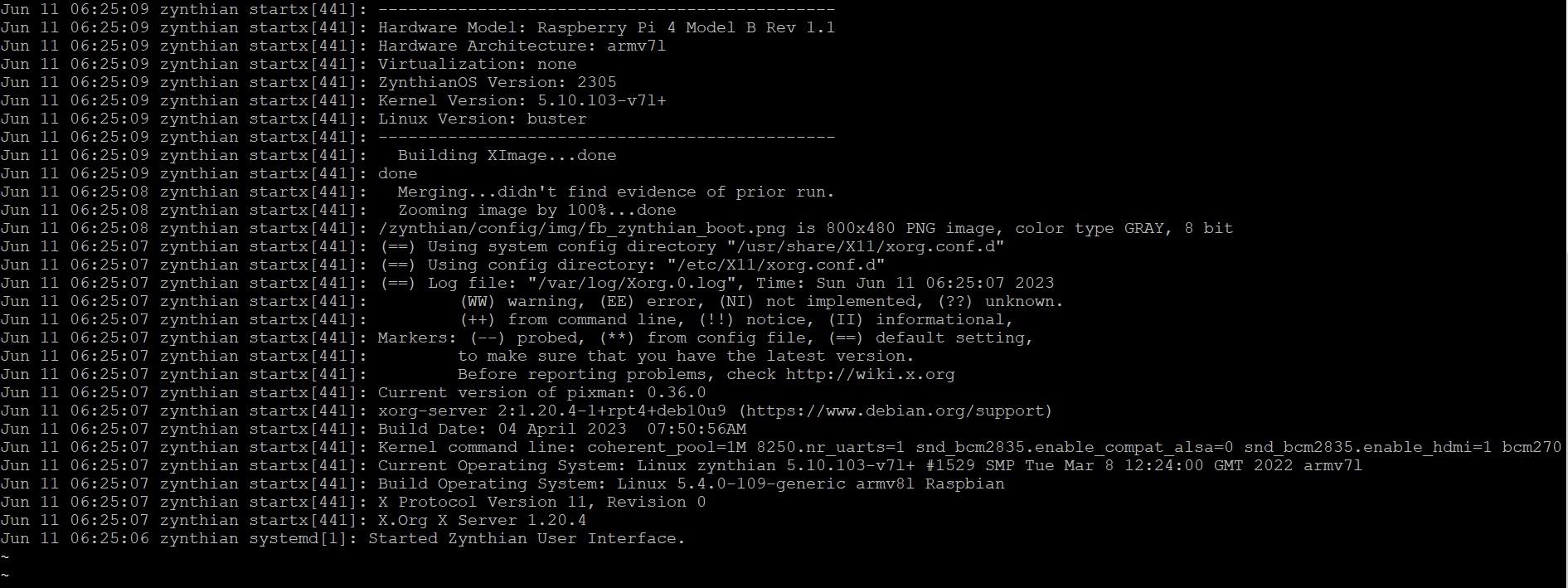
Is there a way to see in the terminal what the card is doing on the SDA and SCL pins?
The expander’s SDA pin goes to the Raspberry’s SDA pin
and the SCL pin goes to the SCL pin of the Raspberry ? Right? They are not like TX and RX which sometimes need to be reversed…
Yes, this thing is already in place. However when I update the pins on webconf, on restart it hangs on the “Restoring state” screen and doesn’t go further… I assume therefore that the pin update doesn’t happen…
Dog goes “woof”
Cat goes “meow”
Bird goes “tweet”
And mouse goes “squeek”
Cow goes “moo”
Frog goes “croak”
And the elephant goes “toot”
Ducks say “quack”
And fish go “blub”
And the seal goes “ow ow ow”
But there’s one sound
That no one knows
What does the log say?
Sorry Riban… can you see from the log if the SDL port is working? Because with the new MCP23017 card nothing worked and now it doesn’t work anymore even with MCP 23008 which worked before. I had to hook everything up to the GPIO…
Not from that bit of the log. Are the boards recognised by i2cdetect? I know you said in the past that they were but it sounds like something has changed.
Both are recognized but do not work. By mistake I pulled the GND wire and disconnected it while hot… at that moment the screens changed as if I had pressed the buttons… So some signal arrives and works, but nothing else works… For now i left all the wires connected directly to the GPIO…
Yes, all the GND of the encoders are connected together and go to the GND of the GPIO, but I also tried to connect them to the GND of the expansion card… but with the tester I see that everything is connected.
Yesterday I was in pieces, and I gave up everything … today I try again, but this morning I wanted to play …
The fact that you seemed to get a valid signal suggests that something is working. (It is plausible but unlikely that a spurious, valid I2C message occurred.) I assume you meant that you got a screen navigation when you had the MCP23017 connected and configured without direct GPI connection / configuration.
I got a navigation screen when I accidentally unplugged the GND wire of the expander and plugged it back in with the Zynthian powered up…
I need to get back to studying the English… thanks for your effort.
…I would keep it like this too, with the encoders connected directly to the GPIO…but navigating the menus, it often goes to the shutdown screen without pushing the shutdown button…
Ugh, I’m not an electronic technician… I want to play my (your) sounds
You could try to use low-level commands to communicate with the device but there be dragons. I am not able to help with that at the moment. There is one other I2C bus in the RPi but it is used for memory access so cannot be used for arbitrary purposes.
Thanks all the same @riban. Maybe I found a friend who sells me a RPi 4 8Gb ram for very little money… so this RPi 4 4Gb goes back to being my OpenMediaVault server… but I’d be curious to understand how I managed to break a port… not I made short circuits, I always did things right… I worry about my mental faculties… or the lack of robustness of the Raspberry…