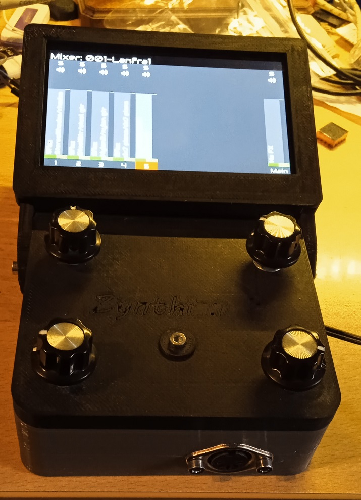
I built a minimal Zynthian with a Raspberry P3 B+ and I have to connect the 4 encoders… Zynthian minimal....😉 - #3 by Lanfranco
I found an MPC23008 chip in the drawer… so I do with this, as I did in the Zynthian I’m using now.
Thanks again for the speed of your replies.
Or you could connect the encoders directly!
I tried but also with gpio readall, but I can’t connect the encoders. I connected the 4 switches and they work.
To find the pins can I ground one pin at a time?
I would have liked to make do but unfortunately I can’t…
To use encoders directly connected you must find 12 spare GPI pins, i.e. not Tx, Rx, I2C or I2S. Then assy these pins in webconf wiring.
I did this on the Raspberry p4 with few problems… but on the P3 it gives me absurd values on the gpio readall…
The switches (which work fine) are connected to the physical pins 37,33,31,36
Which according to the scheme are the GPIOs: 26,13,6,16
While to work, on Webconf I wrote the GPIO pins (thanks to gpio readall)23,27,22,25…
This Raspberry pi3 B+ is the first board I bought years ago… I’ve done many projects with it… Could it be that some pins don’t work anymore?
I still need you… (What a bummer!!!)
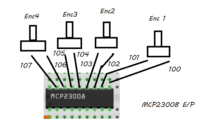
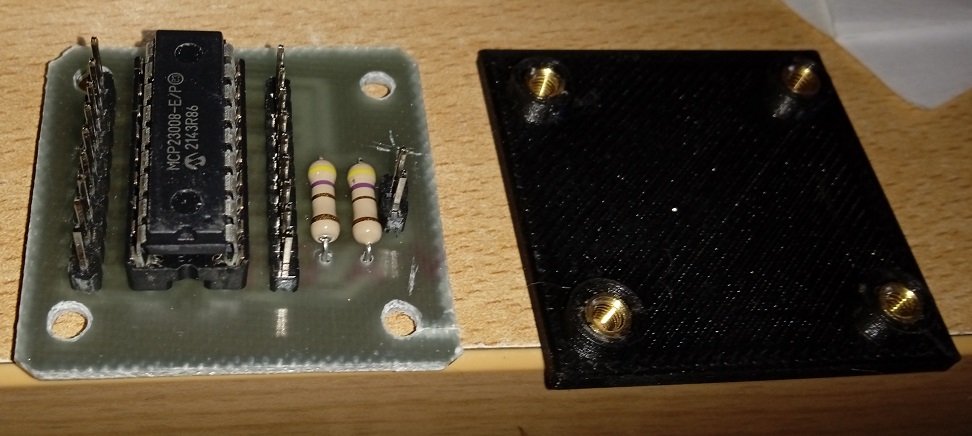
So I connected the 4 encoders to the integrated MPC…
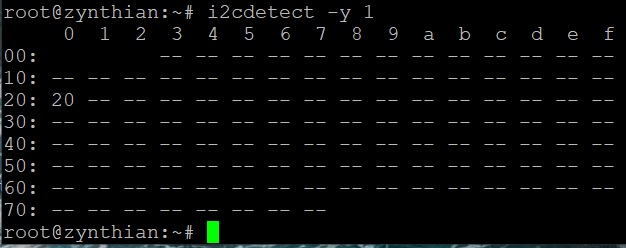
The IC is seen but the 4 encoders don’t work…
I’m not sure that MCP23008 works for encoders. It’s possible that code doesn’t support this config, sorry. MCP23008 was used for switches only in the V1, but it was replaced by MCP23017 when encoders were also moved out of GPIO. You should use a MCP23017 that is well tested and supported for encoders & switches.
Regards
1 Like
Many thanks Jofemodo. ![]()
Oh yes it does. Where even was a special preset in the code known as prototype-kees in the beginning, which was based on the 23008.
Are you really sure? Perhaps if you config the MCP23008 like a MCP23017 and you don’t use the second bank. I never tried…
1 Like
… but Jofemodo, in my first homebuilt Zynthian, I mounted this IC and it works from the first start up…
1 Like
OK. Then, most probably, zyncore lib is managing the chip as a MCP23017, using only the first bank.
1 Like
I solved… this P3 B+ raspberry I had used for a thousand projects and probably there are some pins that don’t work… I swapped it with a P3 B+ that I used for Kodi which is even more recent… now it works all with the encoders connected directly to the GPIO… The damaged one for Kodi is fine…
Thank you
3 Likes
![]()
1 Like
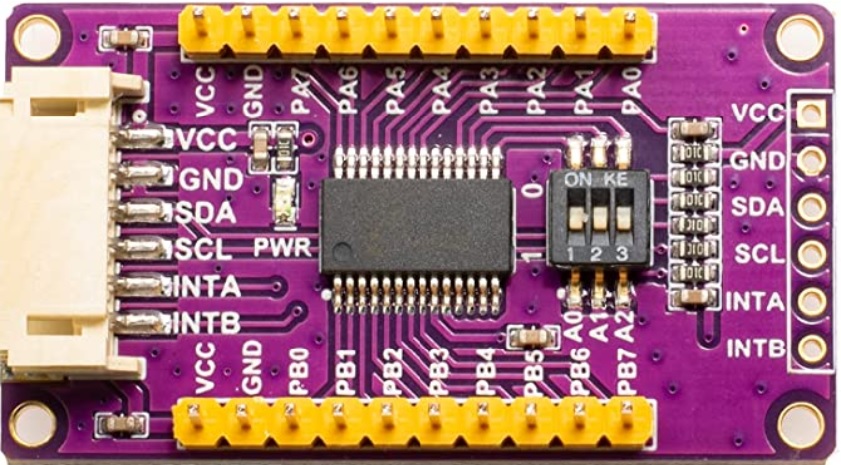
A friend gave me this chip already packaged (MCP23017)… I need confirmation …
PA0… PA7 = 100… 107
PB0… PB7 = 108… 115
… and the three switches ON?
Many thanks
The DIP switches always confuse me. They often have an “ON” indication that when the switch is pushed that way, disconnects the circuit. You can either test the switch with a multimeter or simply connect the device to the I2C bus and detect its address when the switches are in any / each position. I would do that. I gives confirmation the chip is accessible on the I2C address you want to use.
PA0-PA7 are the GPI on port A so will be the first 8 pins configured in webconf. Similarly PB0-PB7 are the GPI on port B hence the next 8 pins configured in webconf. The V4 config assigns these to GPI 100-115 but you can configure in the Hardware->Wiring page of webconf.
2 Likes
Perfect @riban.
Many thanks
HELP!!!
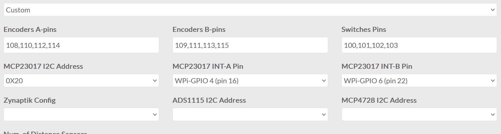
The MCP doesn’t work! I am attaching the links and Webconf settings.
Thanks to anyone who helps me…
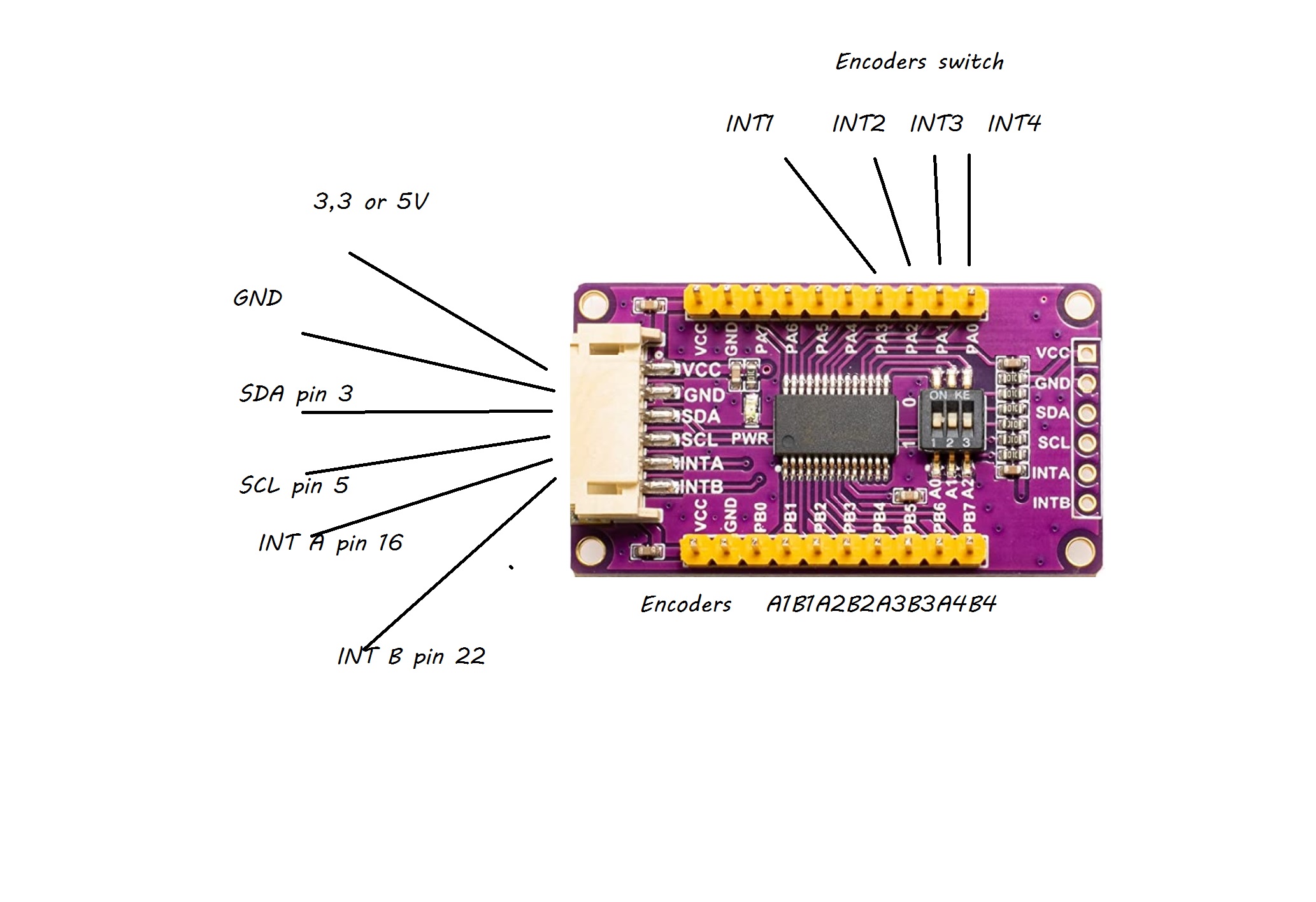
You have written INT1-4. What are they?
Definitely had to be 3.3V, not 5V else you may damage the Raspberry Pi.