Ok, I mounted a 12 to 5V stepdown and soldered the wires to the external GPIO so that I have good contact.
I connected the Zynthian USB cable to the MacBook running MixBus and I saw that it operates perfectly. Now I would like to insert a sound card in the Zynthian but having also connected the 4 encoders to the GPIO, I don’t know if the pins are enough … has anyone done it?
Thank you
p.s.
MixBus sees the Sinth as Zynthian … perfect
This guide is now outdated but includes a description of connecting encoders and soundcard directly to the header. There are enough pins but be careful to avoid any that are assigned for other purposes (I2C, I2S, etc.). You will need to configure the pin allocation in webconf. This has been discussed regularly in this forum so you will find other peoples experiences if you search.
Good to hear you got it working with your MacBook and MixBus. I think the options I referred to are in the development branch so you wouldn’t have seen them. They may be in stable in a different location but it sounds like the feature is enabled by default as you are seeing it work.
You may wish to consider whether there are two power paths, one from your PSU and another from the computer over USB. It may not be a problem but if so, you could use a USB cable that does not pass voltage, only data. The y-cable mentioned earlier is often configured like that but not always. If things are working then you may not need to worry.
Thanks Riban.
Hello everybody.
I just got the Inno Maker HIFI-DAC-HAT sound card and I connected it following a post on this forum. It works great. But now I had to disconnect the 4 encoders (connected directly to the GPIO) because as I expected there are some pins to move. Can anyone tell me if the available pins are sufficient? Before I go crazy looking for them? In the drawer I have an MCP23008 but I can’t find the connection diagram (ERR404) on GitHub and therefore not even the drawing of the pcb that I would make with the cnc.
Thanks for any help.
Lanfranco
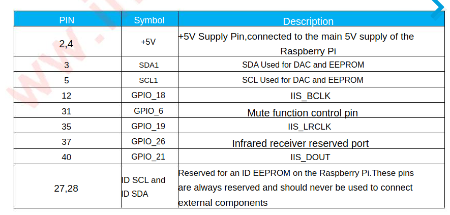
Inno Maker HIFI-DAC-HAT use this GPIO pins. So you can read on their site …
but in the table, the GPIOs do not correspond to the pins of the Raspberry P4…
pin 2,4 +5V
pin 3 SDA1
pin5 SCL1
pin 12 GPIO18
pin 31 GPIO 6
pin 35 GPIO19
pin 37 GPIO 26
pin 40 GPIO 21
these pin numbers do not appear to me …
Yes, I’ve done it several times…
I’m against running zynth’s directly off the GPIO pins, partly for the reasons you demonstrate here.
Since the interface added the S1-S4 buttons, to run a full GUI, requires some mechanism other than straight GPIO pins to access so for full user experience you are going to have to get the soldering iron out at some point.
But as you can see it can be done…
The top two devices have different audio cards in
An Audio Injector in the top case, an hifiberry 50W amp in the later. Both have encoder sets hard wired to pins and they might even bee the same wiring layout.!
You configure the i/o pins in the webconf interface s detailed in the forum.
The layout for the bootm device is detailed in thread
and the skipping round the audio is done right back here with a hifberry amp…
IT can be done but you need a pretty good idea of how it all goes together in the final mounting and that’s down to what you want to achieve…!
as a result of this thread I’m just firing up the aluminium audio injector machine to see how well the encoders behave with the many really good improvements we’ve made recently to the GUI interface which are in the midi-learn branch…
I’ll probably move this chunk of this thread into a new topic if you don’t mind…
Oh look! I have.
1 Like
I thank you for the answer.
I have no problem pulling out the soldering iron, in fact in the post previous to the one you commented on, I was wondering if you could find the diagram to use the MCP23008 and the drawing of the pcb. I can do the PCB with the CNC machine.
Thank you
No worries, I’m probably addressing the thread more to the general search than your specific example, as it’s a a question that comes up a frequently as anything around here.
Do you have any ideas of how you will mount it all finally?
I do have an official zynthian kit that uses direct GPIO connection and its a voyage of exploration to open it when you just want to change the ssd card.
Any pictures yet?
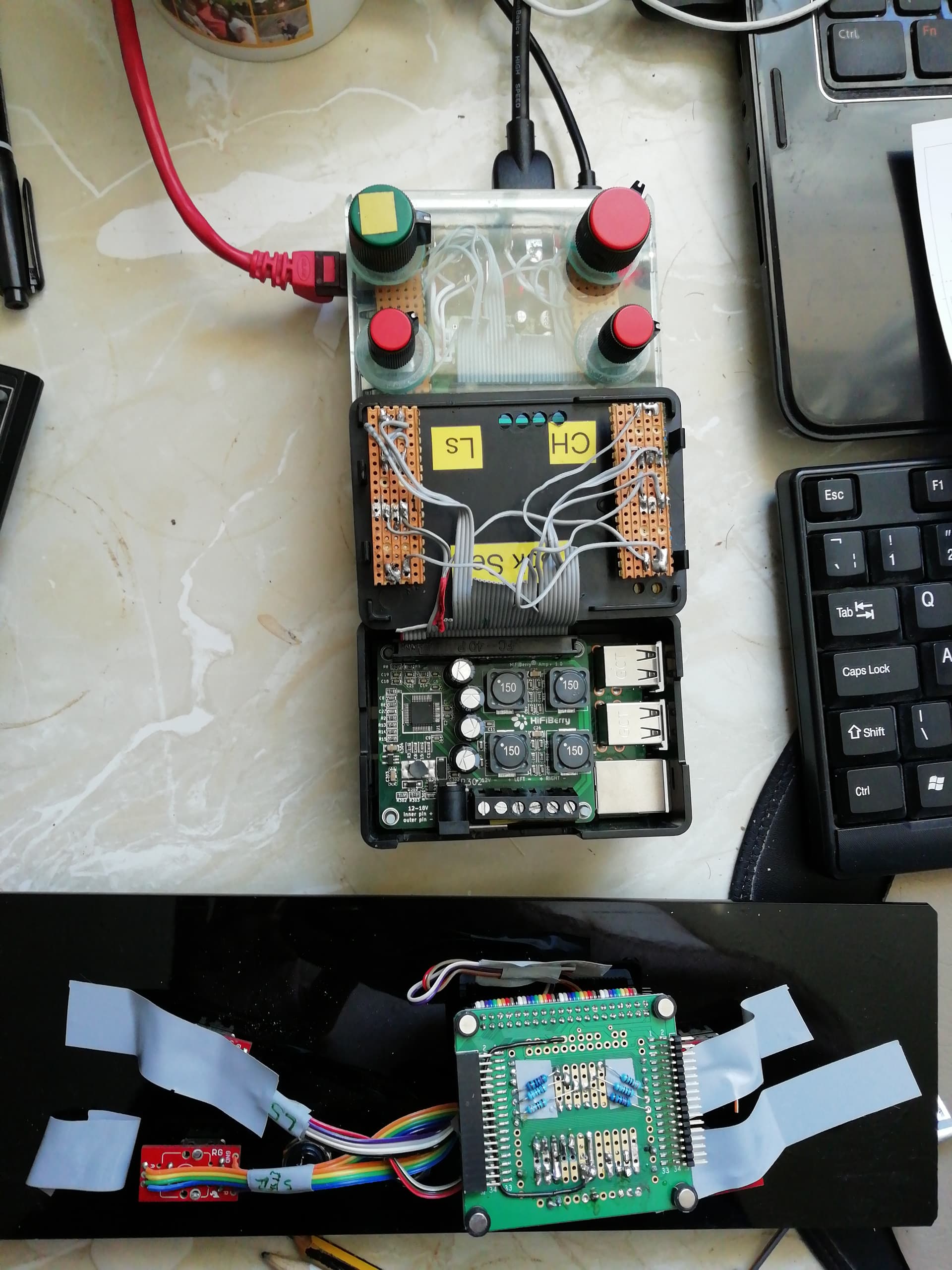
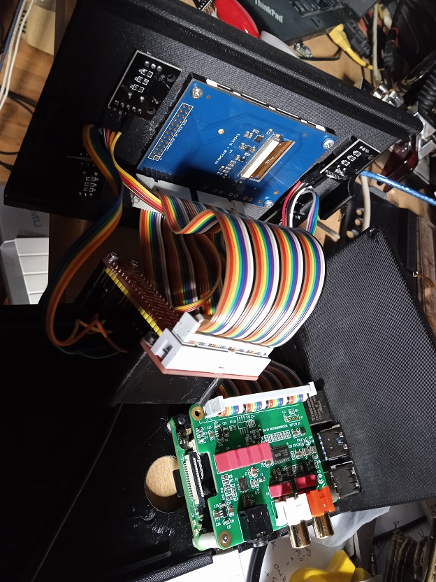
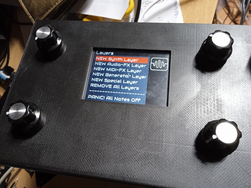
To comfortably extract the SD I made a fairly large hole under the SD. Here is a picture of my Zynthian with the box designed and printed by me … Everything worked, but since I inserted the sound card, I have the problem of the pins …
If it was possible to expand the pins with the MCP23008, I had already thought about adding the new 4 buttons …
You can certainly add the MCP23008 but as you indicate it’s a pretty ancient approach in the zynthian world. You might well be best to look at the very early kit setups (V1) that sort of age cos they used this mechansism and you should see the pins that gets used.
Are all the pins on the InnoMaker
Presumably the data sheet describes the pins for a specific driver ,whilst the zynthian will probably ignore concepts like infra red control.
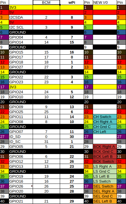
The chart I always worked to is
https://discourse.zynthian.org/uploads/default/original/2X/3/3bcc0c019957a8330938f141a6e0832be1f4cb95.png
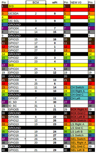
which translates from GPI pins to information suitable for the webconf interface.
You say you have hand the encoders working without the sound card? What were the webconf pin settings that worked ? because, presumably, you want to change as little as possible ?
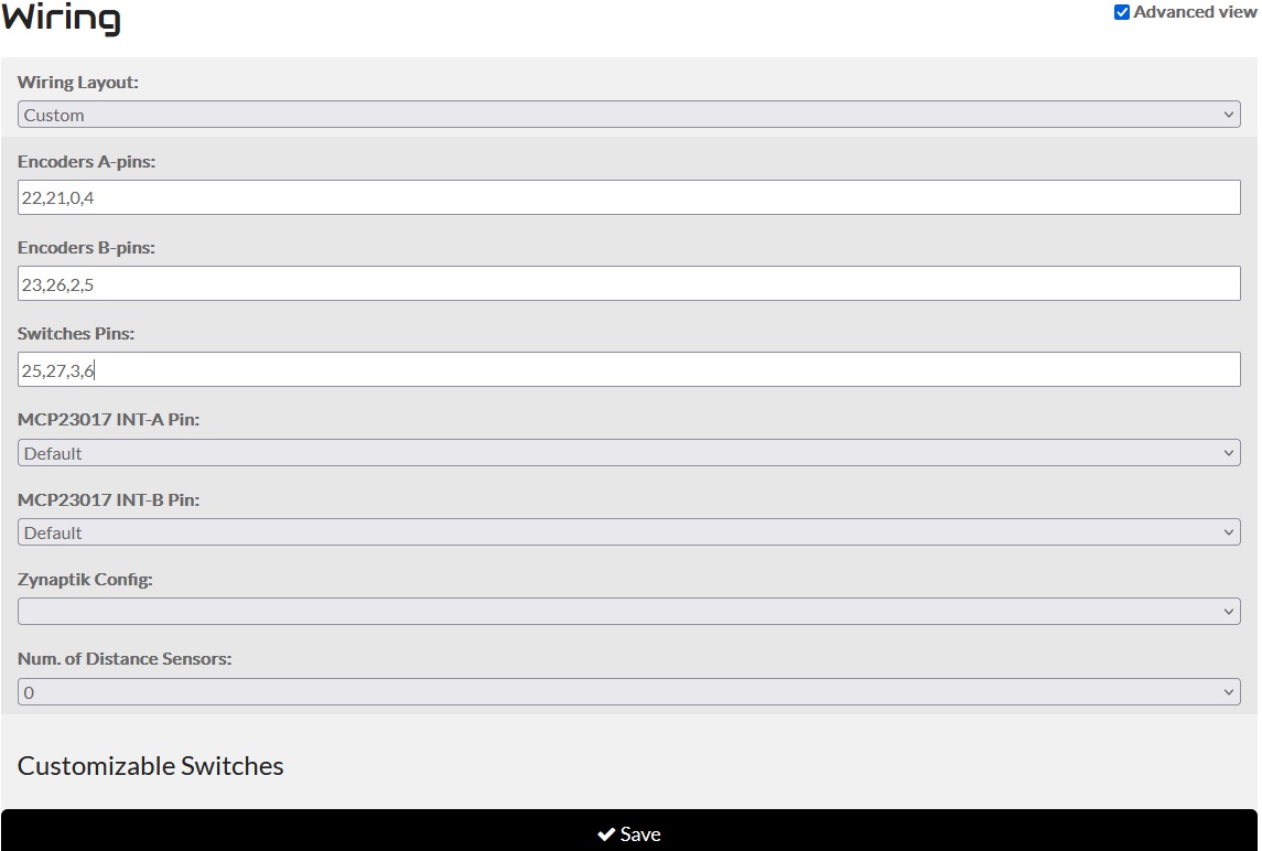
They are now set up as follows:
A - a 22
b 23
int 25
B- a 21
b 26
int 27
C- a 0
b 2
int 3
D- a 4
b 5
int 6
I am using an Adafruit 2.8 resistive display
If I select Dummy on Wire everything works …
Plug in a mouse.
Can you get sound out of the zynthian?
The test audio in the admin screen is probably the best place to start.
The audio is perfect. no problem. The problem is finding pins for the four encoders.
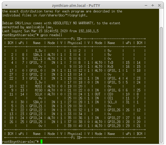
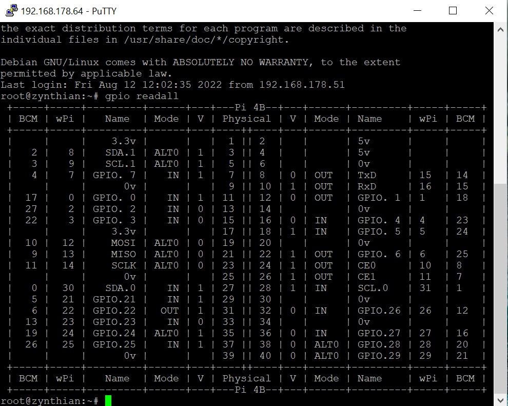
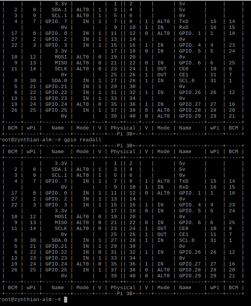
Run a terminal and have a look with gpio readall
That should indicate the current state of the pins whilst running the zynth…
1 Like
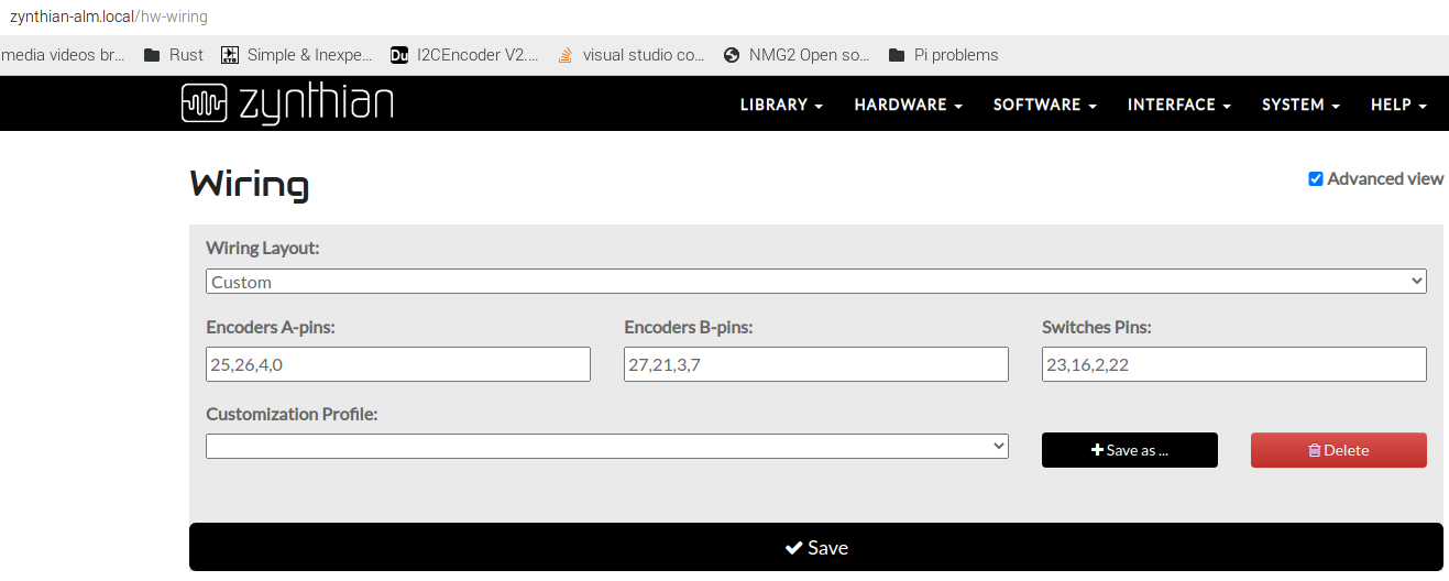
Can you give a screenshot of your advanced wiring set up?
This is mine from the audio injector machine.
Now, and this is very much from memory the best way forward is identify the select on/off switch press. Once you have this you can progressively add the other bits and pieces…
The trick (from memory) is to use 0 for pins that you don’t use…
So you are looking for the pin connected to the select encoder and you wish to map that through to any switch setting…
So you are looking at values in a custom set up for the switch…
here is gpio readall run before and after I’ve pressed the select encoder switch…
Notice the change in pin
| 6 | 22 | GPIO.22 | IN | 0 | 31 | which changes from 1 before pressing to 0 after pressing and holding.
This is the select switch…
But I’m still trying to get a working zynth on this machine to confirm the actual results…
To do this, you re-issue the command while holding the button?
The selected pins look okay. Have you connected the encoders thus?
| Header Pin | Encoder |
|---|---|
| 31 | Encoder 1 A |
| 33 | Encoder 1 B |
| 37 | Switch 1 |
| 29 | Encoder 2 A |
| 32 | Encoder 2 B |
| 36 | Switch 2 |
| 11 | Encoder 3 A |
| 13 | Encoder 3 B |
| 15 | Encoder 3 Switch |
| 16 | Encoder 4 A |
| 18 | Encoder 4 B |
| 22 | Encoder 4 Switch |
And connected 0V/Gnd to the other side of each switch and the centre pin of each encoder?