I’ll to try the removal of all resistors and to test again. Thanks for your help!
Hi @wyleu! I’ve changed the partner to my zynthian. I’m using the motor 61 with ipad to minor gigs and other setup with more keyboards and gears. I’ve bougth a brazilian clonewheel organ (TOKAI TX5) two months ago to decorate my living room and the zynthian will be the best choice, once the organ doesn’t have other sounds than hammond simulation.
But anyway, I’m following your discoveries and tests about the Motor 61. It’s a great controller and I’m falling in love by it. Please keep your tests, they will help a lot of people like me.
1 Like
Ohoho! My Motor 61 is on the way … jejeje! As soon as i have it, i intend to implement the MIDI-feedback so we can have nine motorized drawbars for setBfree 
3 Likes
#TeamBehringerMotor jajajajajajaja
Getting Program Change out of it is a little involved. . . .
The suggestion is use the pads.
Hey,
i had the same issue like jonathaslacerda with the KY-040 Encoders. I removed all 3 resistors. It works! 
Thank you!
1 Like
Yes remove all resistor R1 R2 R3 but replace with capacitor switch 100 nf data and clock 10 nf
MidiYodi ( https://www.midi.org/forum/545-midiyodi-midi-file-editor-and-examiner )
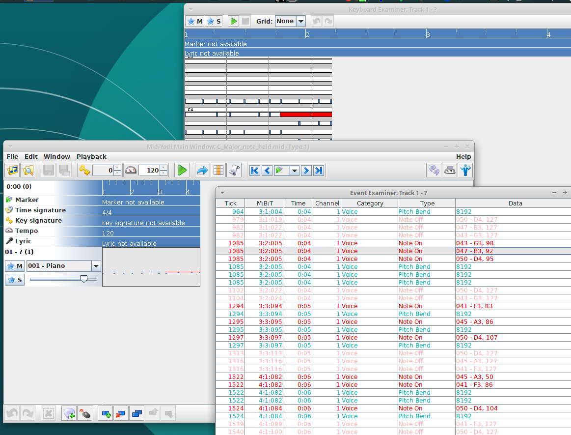
Indicates there’s a held note of the Motor 61 but only when connected with USB ( seems ok on 5pin out)
C_Major_note_held.mid (401 Bytes)
From Zynthian MIDI capture.
I presume I better try and duplicate without any Zynthian component involved…
Capacitors? I don’t think so, but won’t hurt if you add some. After puzzling with KY-040 encoders and zyncoder.c file i have feeling, that software fixes this - reading data from i2c bus takes some time and interrupt register cleared / new interrupt may be fired after transmitting previous data register content (paragraph 3.6.4 from Microchip datasheet). Looks like this time is enough to eliminate bouncing problem, but software developers can give better explanation.
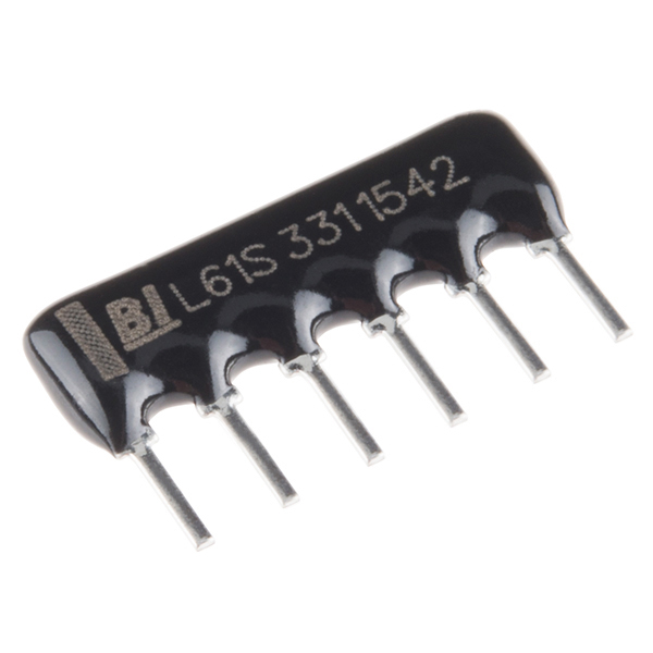
Weak MCP23017 internal pullup theme remains - 100k is barely enough. Next reincarnation of All_In_One board are better when those resistor networks can be added - something in 10k…20k range.
yes you are correct the encoder module is modified so that it can function perfectly in zynthian, if only just removed the resistor is too sensitive not to function perfectly
do you have the mcp23017 example image or schematic as you described here [network resistor] (https://cdn.sparkfun.com//assets/parts/5/8/6/8/10855-01d.jpg) can be added - something in the range of 10k … 20k. ky rotary encoder switches the module image
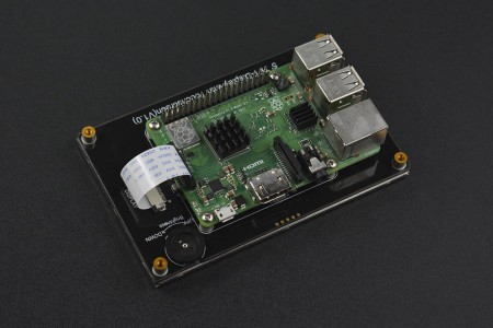
Will this be next official or at least supported LCD for Zynthian box? 5 inch capacitive touch and DSI interface. So far only LCD for Pi with DSI connection was 7 inch screen.
Link to distributor Wiki page.
Nice to see bigger screens than the kits !!
It’s not difficult to add a new screen description, it really just the results of someone on the forum writing up how they got it working.
The biggest issue outside of seeing a picture issue, is how one might mount the screen in something that one dare take near a stage… That’s what’s been mucking up my 7" progress. There are several nice plastic extruded cases but something that one can mount four encoders (and the new panic switch  ) within such a formation that one can also grant easy access to 4 USB’s ethernet, power & audio in/out without tedious extender cables is a fairly involved piece of design. the DSI Interface furthers adds to the complication because if you get the board in place the sockets are underneath the screen.
Probably the closest I can easily get is a 7" display audioless zynthian linked over ethernet to a sperate zynth elsewhere doing the audio stuff. . . .
DSI Interface furthers adds to the complication because if you get the board in place the sockets are underneath the screen.
Looking at pics and specifically this image, DFRobot 5 incher goes other way around, Pi bottom is on LCD side and probably DSI cable length leaves a bit to play with entire unit placement.
Finally I could to test the resistors removal from KY-040 and like @masterkey told previously, worked like a charm. Now I’ve three things to do: build the case, build an arduino based usb-midi controller and maybe upgrade the raspberry to latest version (3B+). The zynthian gorgona image most recent works with raspberry pi 3B+?