The new All-In-One PCB is ready

Hi @Zynthianers!

The new All-In-One PCB is ready for production! :tada::confetti_ball::tada:

The first printed boards were buggy and i had to disable 2 MIDI ports for not burning my table:

:blush::rofl::rofl:

I just received the fixed one and it works like a charm:

So, i’ve ordered a few of them for all of you :wink:

These are the features:

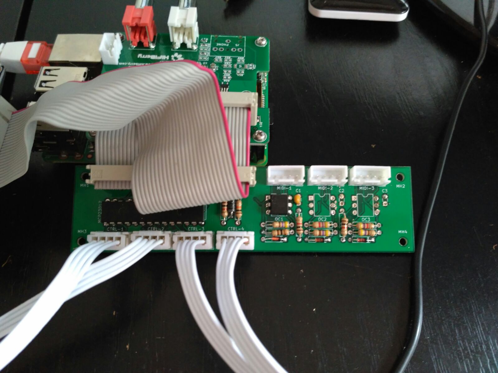
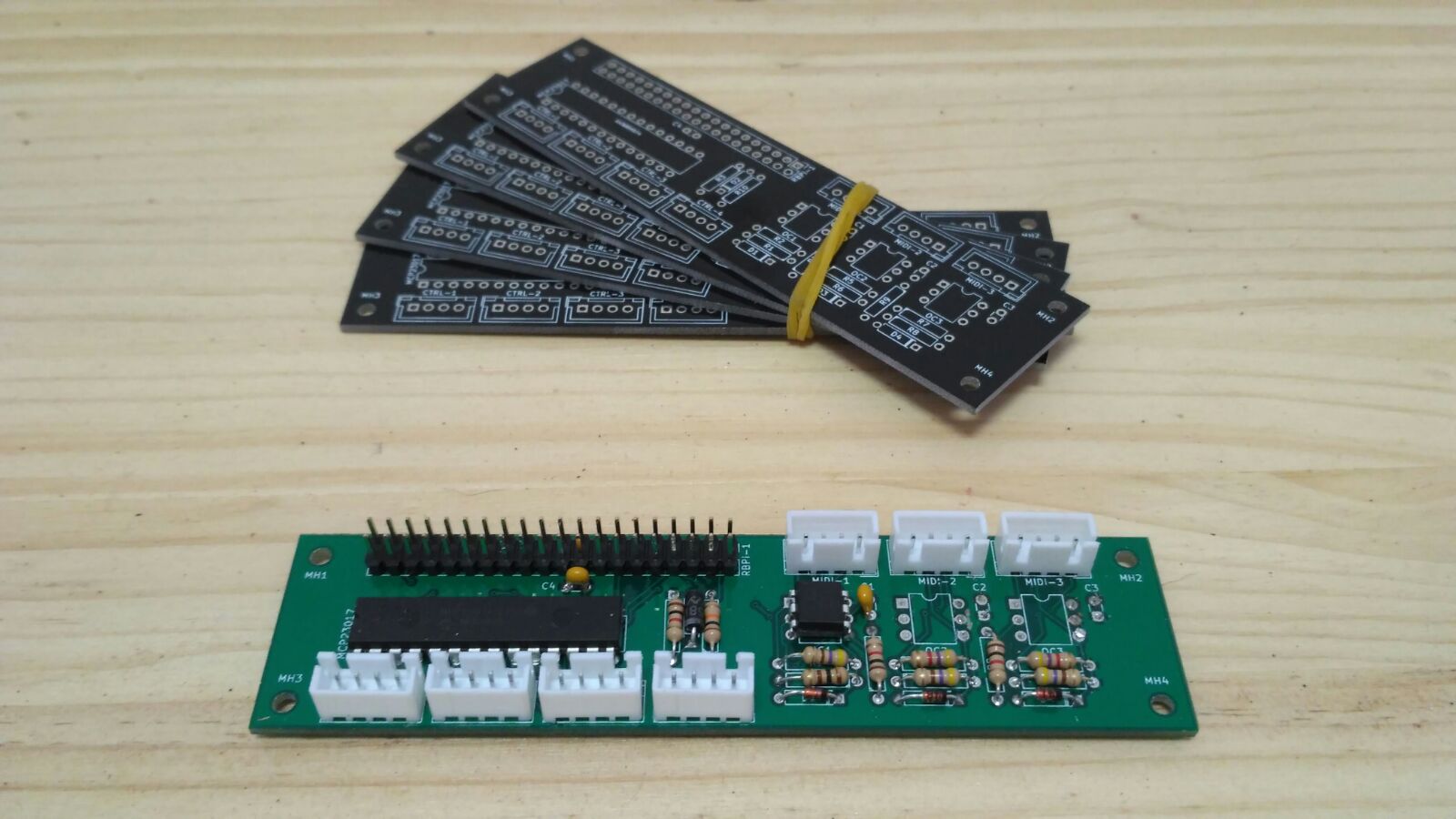
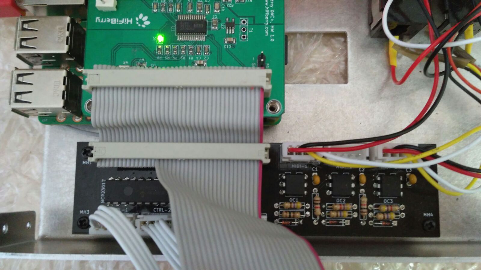
  • A GPIO expander MCP23017 is used for managing all input from encoders and switches. Only I2C pins and GPIOs 25 & 27 are used.

  • It includes 3 standard MIDI ports (IN, OUT & THRU) with optional activity LED. UART pins (TxD & RxD) are used for this. All the 3 ports are opto-coupled following the scheme shared by @Imager :wink:

You can find the project files in the HW repository:

zynthian-hw/zynthian_allinone at master · zynthian/zynthian-hw · GitHub

This is my first KiCad project and probably it’s a complete mess for a good electronic dessigner :blush: Anyway, i’m really happy with my new tool and i hope to bring more and better PCB designs to the community in the near future …

Enjoy!

10 Likes

Nice work! I’ll need to check one out for my next build.

2 Likes

Great!! I think your project reached a professional grade sometime ago. Specially worth to mention is the fact that you accept to develop new feature requests which is an valuable extra.

Congratulations…once again.

Regards, Jose.

2 Likes

this is nice and clean design, great job !

Hi @Zynthianers!

I made a PCB only with the connections for the encorders:

Note: This PCB has not yet been verified.

Regards, Rod

1 Like

Nice! If you could share the design files … :wink:

Of course! :grinning:

I’m going to do the assembly of the PCB this weekend. If it works, I share the files in github

1 Like

Ooooh this looks nice! @jofemodo does it work with the current case layout?

Your PCB looks really nice.

Of course a complete ALL-in-one board would have:

  1. Connections for encoders
  2. MIDI connections and circuitry
  3. Connection for touchscreen LCD display
  4. PCM5122 audio chip and associated circuitry https://easyeda.com/feather/Raspberry_pi_DAC_PCM5122-rNVdTN5Z3
  5. Connections for audio output jacks

Perhaps similar to this:

1 Like

You should make new mounting holes for the PCB …

Regards,

Jeje! You read my mind … :wink:

Does the all-in-one replace the 4 controller-pcbs as well as the 2-in-one pcb?

No. It replace and extend the 2in1 PCB while improving and simplifying the wiring.
You still need the 4 controller PCBs, but soldering a JST connector instead of an angle-row-pin.

BTW, I’m working in an updated version of the mounting tutorial.

Regards,

So does this solve the GPIO issue to be able to use PiSound etc?

Yes. Only GPIO 25 & 27 pins are used, so i think you could use any soundcard without problems.

Very nice, I was looking forward to this stage!
So I have to decide which soundcard to use now, and I could just start building :slight_smile:

So we can produce an Encoder/MIDI interface to go next to our HDMI monitor with seven connections?

+3.3V
+5V
0v
SCL
SDA
INT A
INT B
?

I would say “yes”, but i haven’t tried yet. Anyway, you should be aware of not using a cable too long.

if you want longer cable, you can try with TI p82b715 I2C extender
I’m evaluating them right now for another project

1 Like

I confirm they work perfectly (>5m cable with flat RJ11 cable)

1 Like