Hi @zynthianers and specially V5 owners!!
The V5.1 release is getting closer and i would like to offer an upgrade path for V5 owners.
As i already commented here:
releasing a “full upgrade kit” is “logistically complex” and really wasteful, so very probably we are not going to follow this path.
In the other hand, the Minimal V5 Upgrade Kit is super cheap, logistically easy to manage and almost no wasteful, so i would like to follow this path.
This path is harder and probably not many V5 owners would take the risk. Having good documentation would help, specially a decent video tutorial. The problem is i’m quite busy and i don’t know when i would have the time to record a decent video tutorial. As you probably have noted, i’m not a “video guy” ![]()
To “unblock” the process, i’ve prepared a kind of V5 Minimal Upgrade Guide. Indeed, in its current state, it’s more a draft, but it’s best than nothing. If some of you, brave tinkerers, are interested in going forward with the surgery, i would send the parts for free with the hope that you kindly help me to improve this guide and hopefully record a decent video. Simply contact with me by PM.
OK! Let’s go!!
Here comes the step by step procedure i followed with one of my V5 units to get the first V5.1 proto:
0.) Disassemble the bottom part of your zynthian V5 until having the bottom case and the main board in its original state. Take care of not losing any screw, etc.
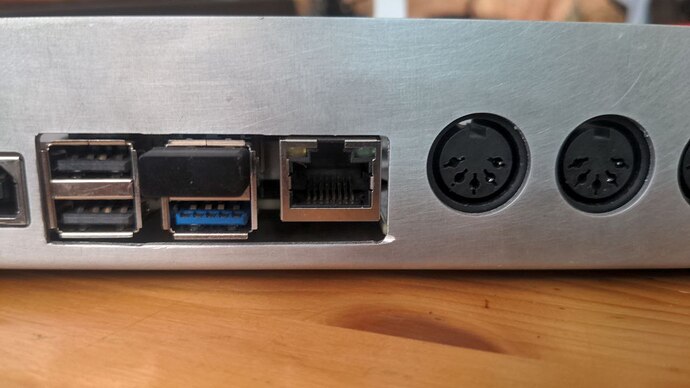
1.) Cut the bottom case. You need to make bigger the Pi5 holes. Like this:
I would recommend to first draw/mark the cut on the case, then use the dremel, slowly but fearless. You are doing the right thing ![]()
This is the result i got with my limited skills:
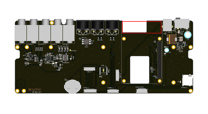
2.) Cut the main board. Note that you will cut the 2 data tracks going from the RPi to the USB-B port. We will repair this in step 3.
Again, mark the cut on the main board and proceed with the dremel, no fear!! You are only cutting 2 un-important tracks!! ![]()
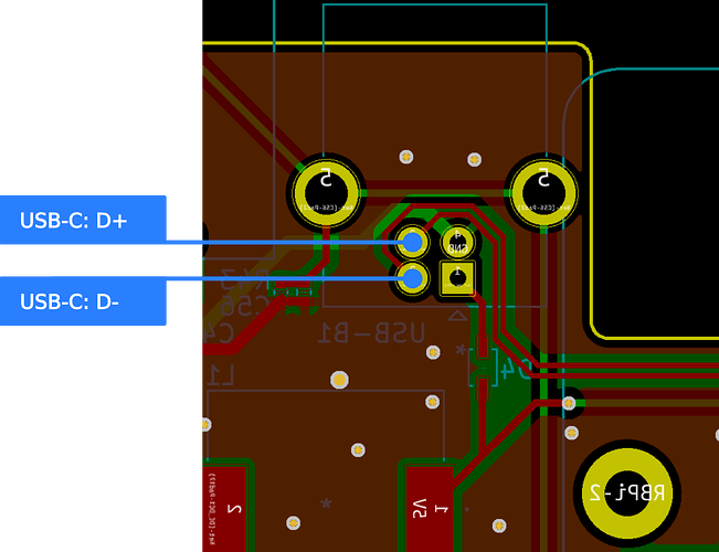
3.) Solder the USB-C harness data wires to the right pins in the main board. This will fix the little disaster from the step 2. Use some hot-glue to secure the join and avoid accidental de-soldering.
This step is still untested. I’ve ordered a few harnesses from aliexpress to test if they work:
but i had not the time to test yet.
The color code for the harness is:
- Green → D+
- White → D-
- Red → VCC (5V) → Unconnected. Take care of short circuit with some tape!
- Black → Ground → Unconnected. Take care of short circuit with some tape!
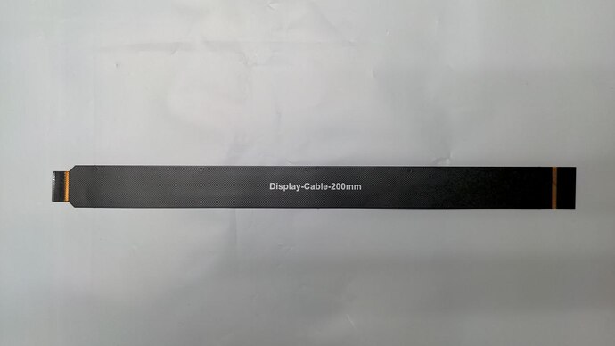
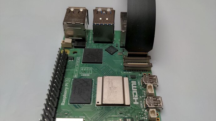
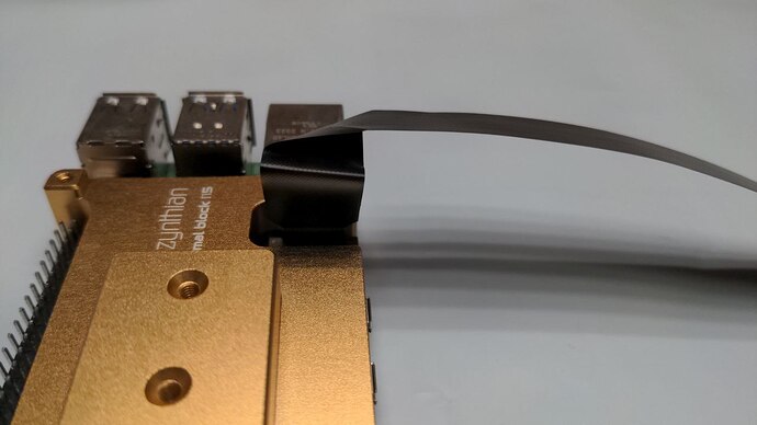
4.) Plug the new display cable in the RPi5.
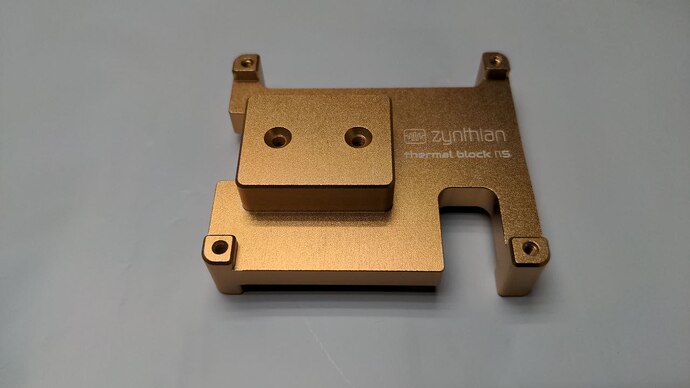
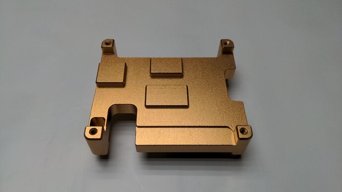
- Mount the new thermal block in the RPi5. The procedure is described in the V5.1 assembling tutorial. The needed thermal pad will be included with the new thermal block. Remember to save a piece for the bottom-contact surface.
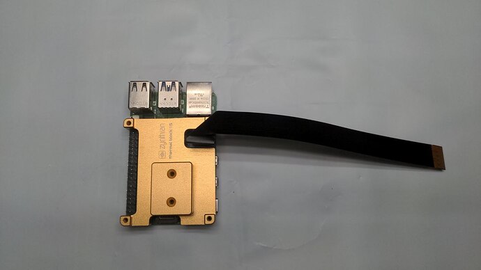
6.) Bend the display cable so it go out in the right direction and orientation:
7.) Fixate the RPi5 + thermal block onto the main board and attach the main board to the alucase bottom part as explained in the V5.1 assembling tutorial.
- Don’t forget to stick the last piece of thermal pad in the thermal block before plugging the RPI5.
- Don’t forget the 2 screws that secure the thermal block to the bottom case. This is very important to get a good heat dissipation towards the alucase.
- Find a way to pass the USB-C harness so it can be connected to the RPi5. This has to be explored!
8.) Connect the SD-card harness and the USB-C harness. There is a chance that the SD-card works with the extender. If it works, lucky you!!! If not, you should plug your SD-card directly to the RPI5. The good: it will be ultra-fast!!!
9.) Connect the bottom and top V5 parts. It’s described in the V5.1 building tutorial.
10.) Close and test!
And that’s all. Kind of trivial, except the first 3 steps. I’ve all the needed parts.,if some of you want to try and help with the tutorial, i would send the parts for free.
Enjoy!

