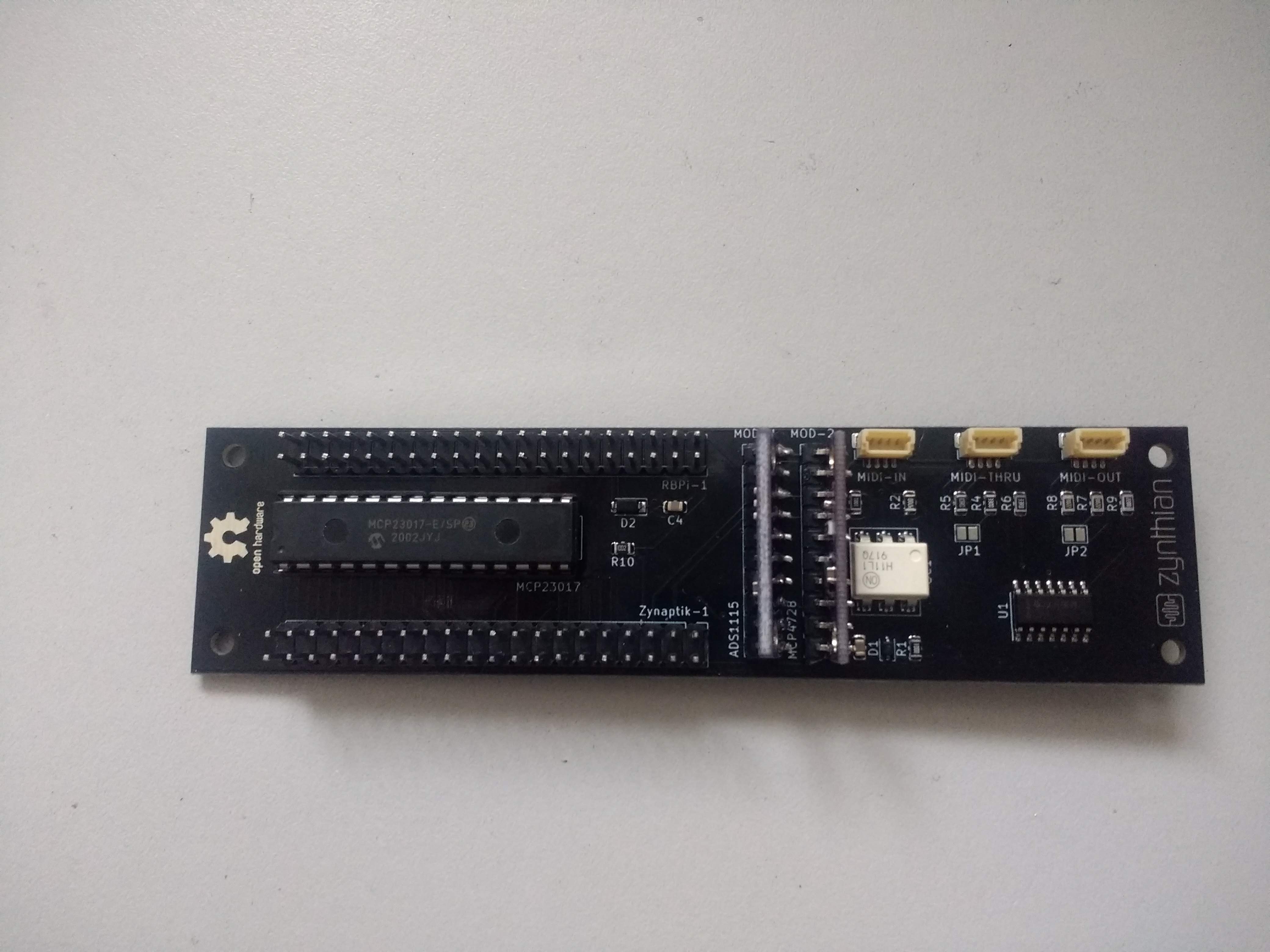
I’ve released a little kit for customizing the zynaptik module:
With this little kit you can add the extra features to the zynaptik module:
16 extra digital I/O pins (GPIO => MCP23017)
4 analog input pins (ADC => ADS1115)
4 analog output pins (DAC => MCP2348)
The software implementation is quite advanced and currently you can:
Use the I/O pins as extra switches, assigning to CUIA or MIDI events
Use the 4 analog inputs as CV, assigning to MIDI events (CC, Pitch-Bend or ChanPress)
I’m working for improving the CV/Gate implementation and very soon you could use the digital pins as Gate In/Out. The DAC (CV-out) remains unimplemented until now.
Take a look to:
I would like to not being the only one testing these features …
@jofemodo there needs to be more information about how to install the Zynaptik Expander Kit. I believe it comes as 6 parts:
MCP23017 IC
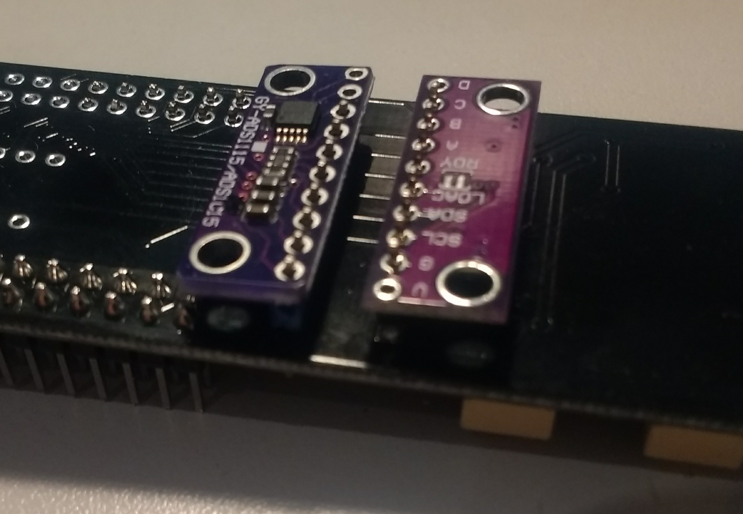
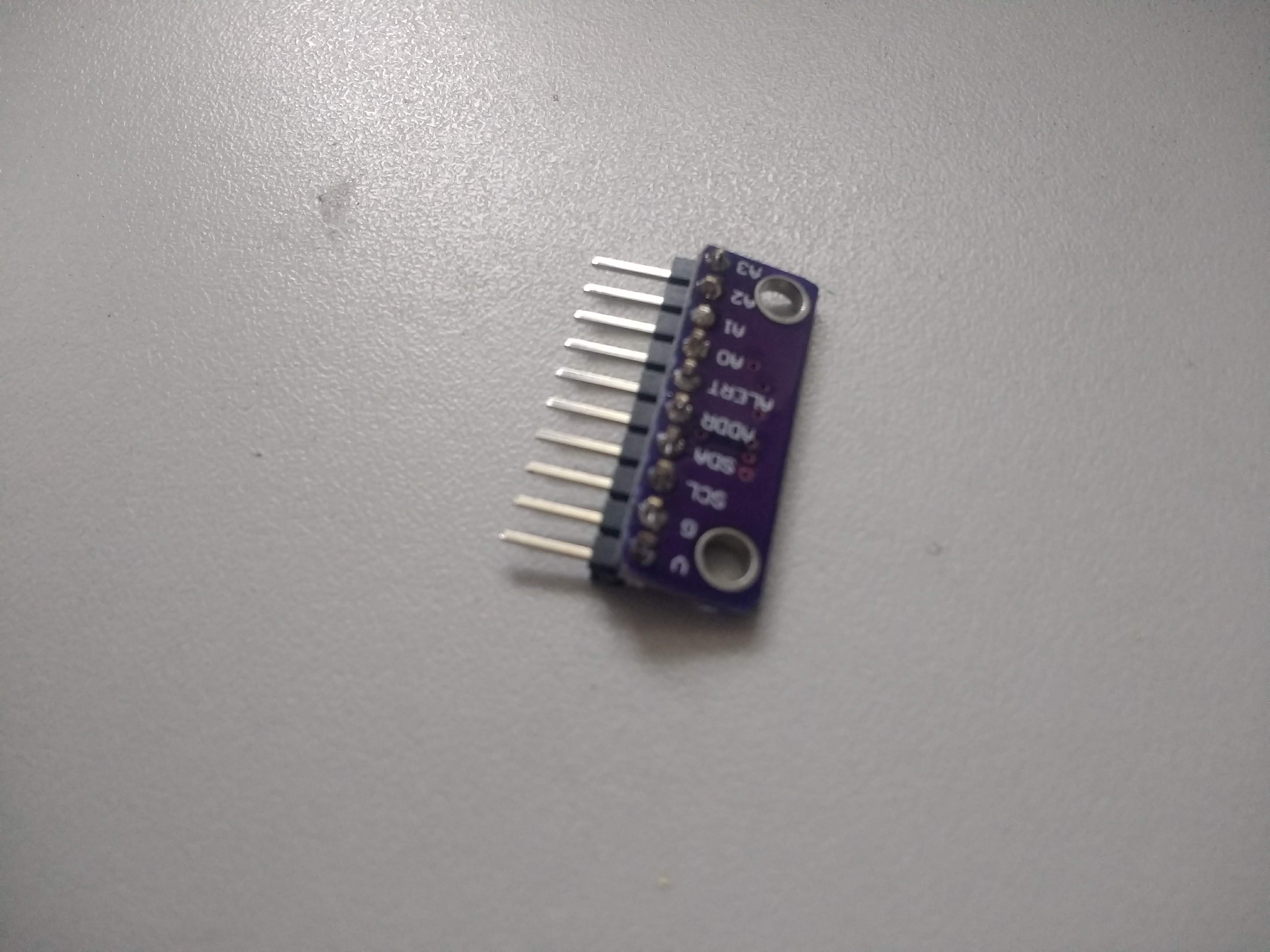
ADS1115 analogue input module
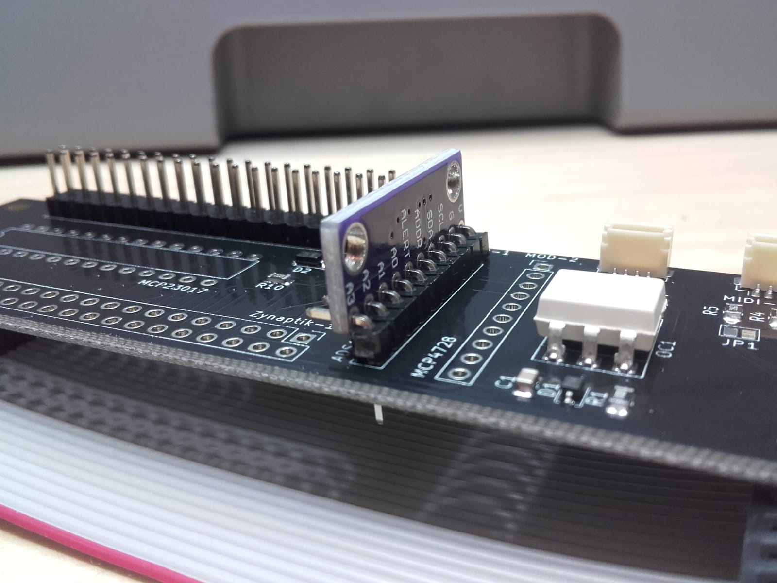
MCP4728 analogue output module
40 pin DIL header
2 off 10 pin 90 degree SIL headers
I think this would benefit from a 28 pin DIL IC socket to avoid the need for (possibly novice) constructors to solder IC directly - possibly the highest risk of damage to components and difficult to reverse (remove IC) after soldering. (I am going to use 2 off 14 pin DIL sockets because I don’t have a 28 pin. This works fine.)
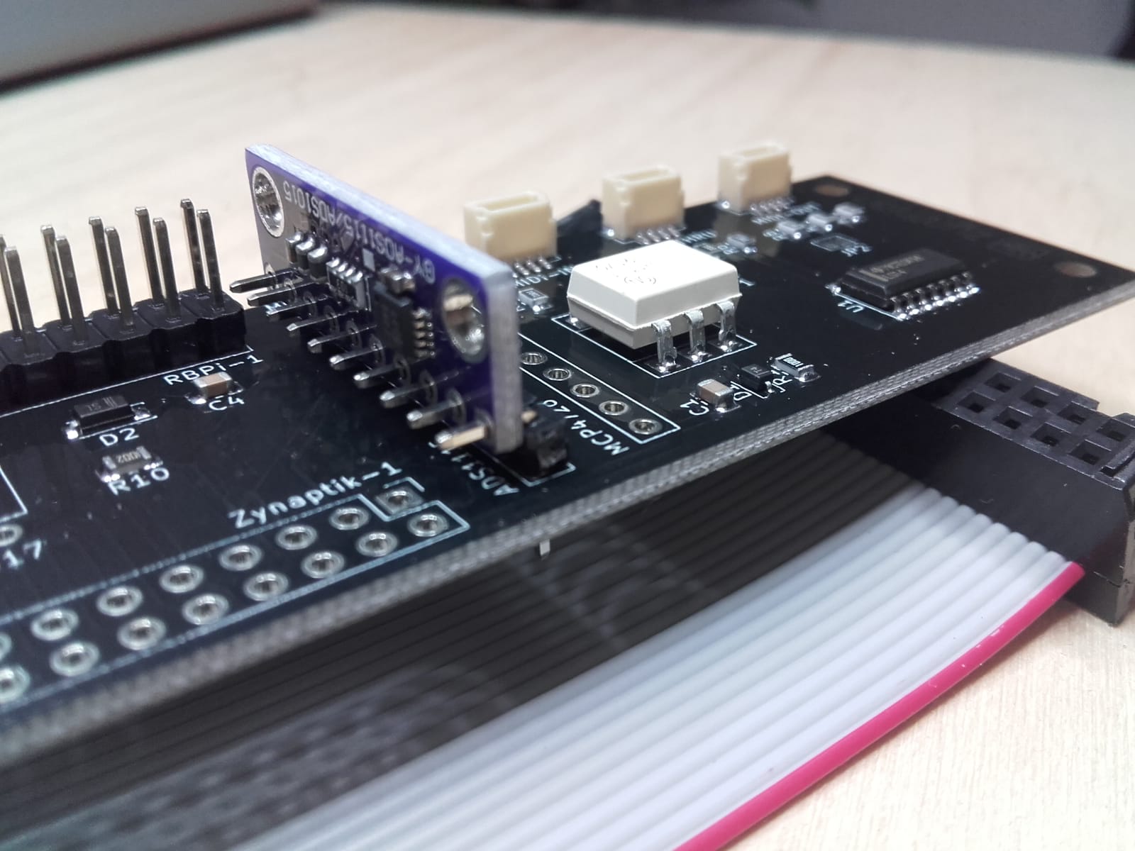
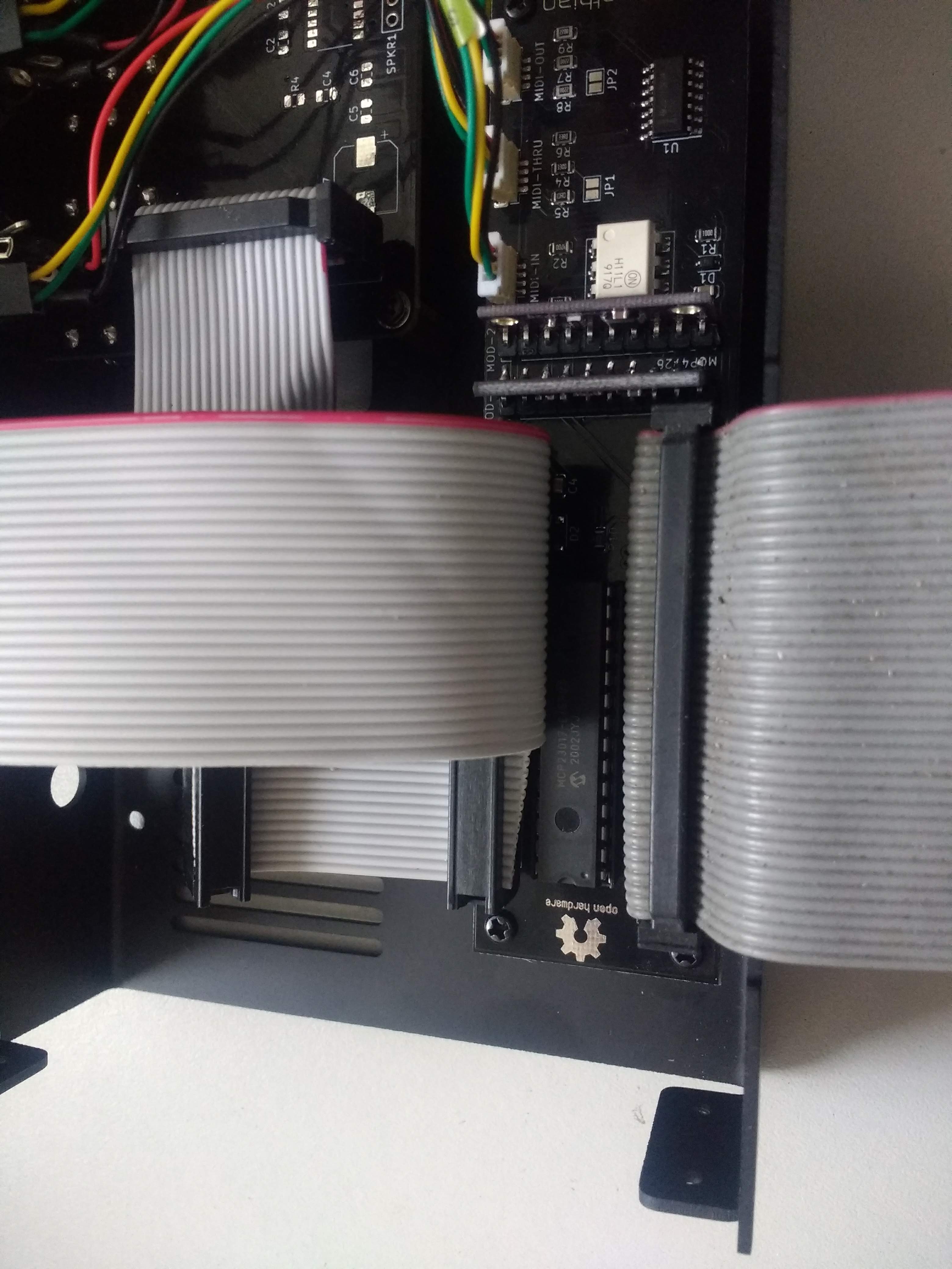
The two modules presumably are meant to be soldered to the 90 degree headers then soldered to the Zynaptik board. We need to know the orientation of these modules. I can see no documentation or indication on the modules as to which way they should be connected. I also cannot figure out how to insert them without interfering with other components or connectors. Further, I think these too would benefit from SIL sockets soldered to the Zynaptik board allowing simpler construction and replacement in case of fault.
I’ve tried to fit these modules every which way and can’t figure it out! Once there are answers the wiki needs updating.
There also needs some description of how to get the contacts out of the case. Maybe you can’t in which case the description may explain these are for internal use or modification to the case may be required.
[Edit] The modules might fit underneath the Zynaptic board. A little unorthodox but it might work. Just tried and it is a bit too tight fit when mounted upright with 90 degree headers. Maybe with straight headers so they sit flat but I think that would also foul the bottom. Such a configuration may require one on top and one on bottom. I guess you have managed to make this fit some how.
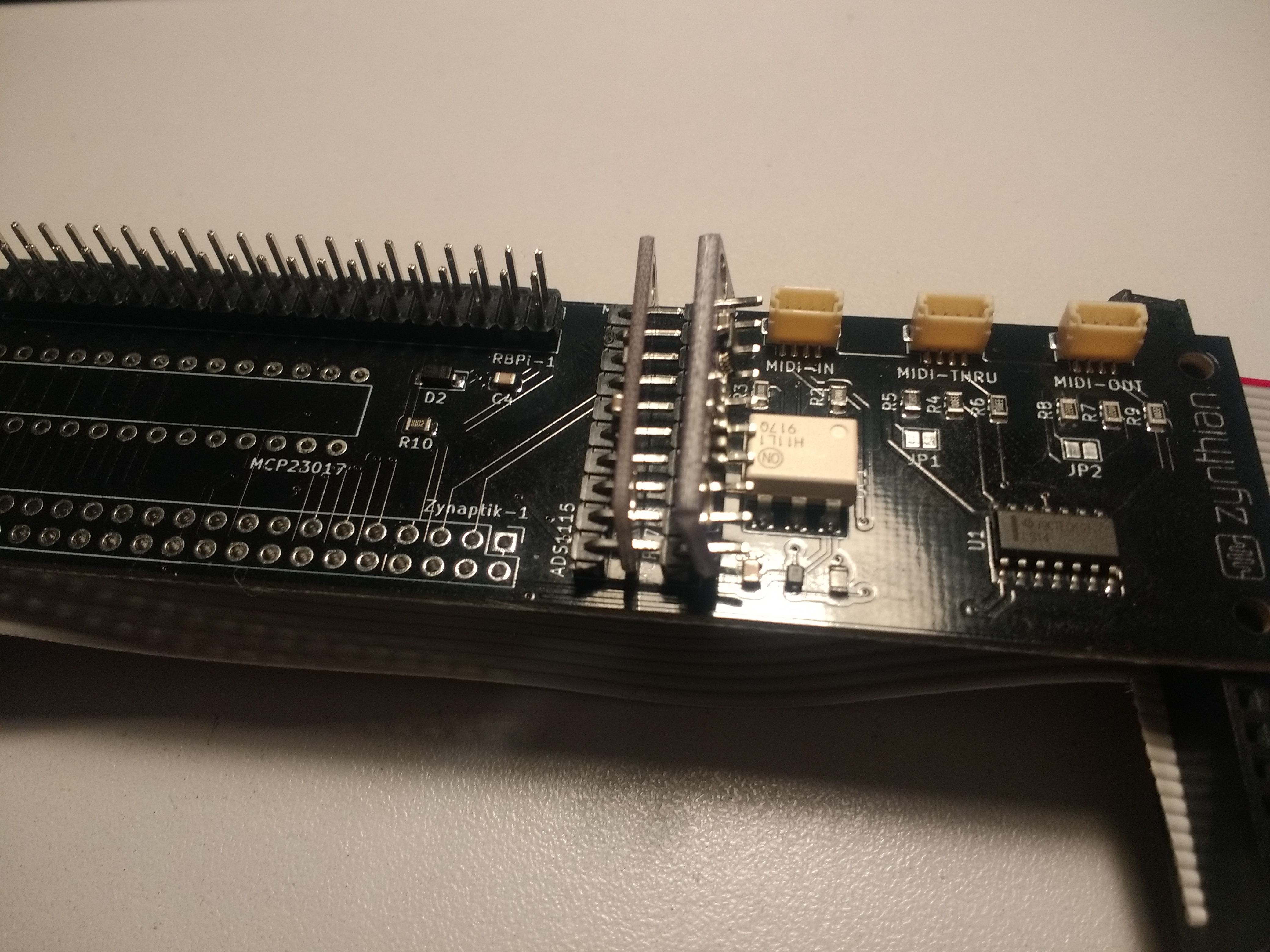
Modules attached to bottom of Zynatptik board, mirrored to fit so one is component side down. Using straight header pins. Cannot fit sockets so would need to solder directly.
Regarding the orientation, VCC is pin 1. It can be easily founded with a multimeter or taking a look to the zynaptik schematic, but … YES, you are absolutely right about the lack of documentation about mounting the “Zynaptik Expander Kit”. It’s a quite recent “addition” and it’s mainly intended for advanced users (by now), so i didn’t feel any pressing for writing docs. Now i can feel some, so it’s a good moment for it. Anyway, if you want to help me with this, i wouldn’t say “no”
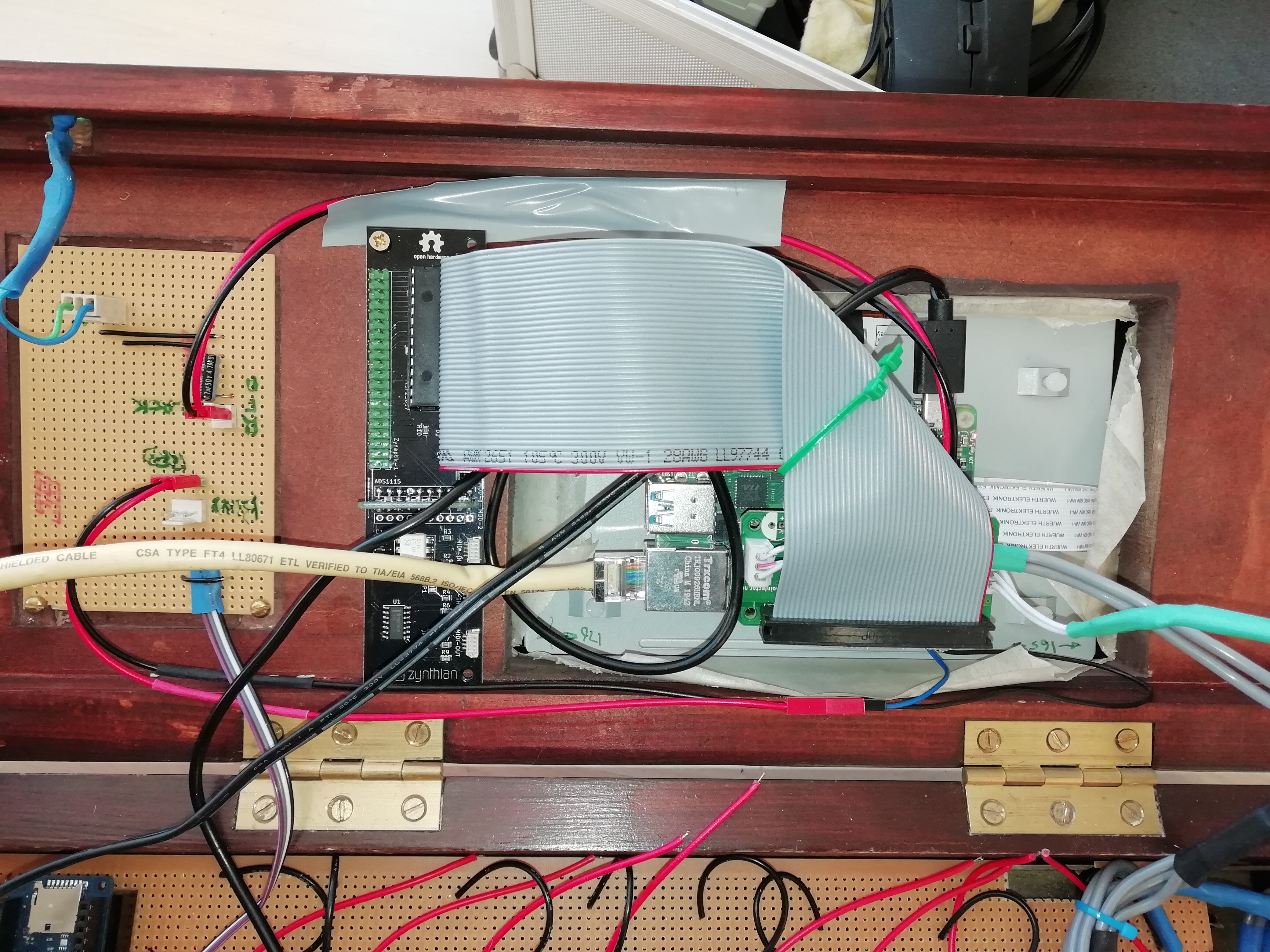
Ahhh! Regarding the connection of the zynaptik with external sensors, switches, etc, i would suggest to use an old-style “IDE” cable. There is a groove in the alucase’s front especially designed for this.
If you don’t have an IDE cable in some dusty box forgotten on some dark corner of your garage, i could send you one
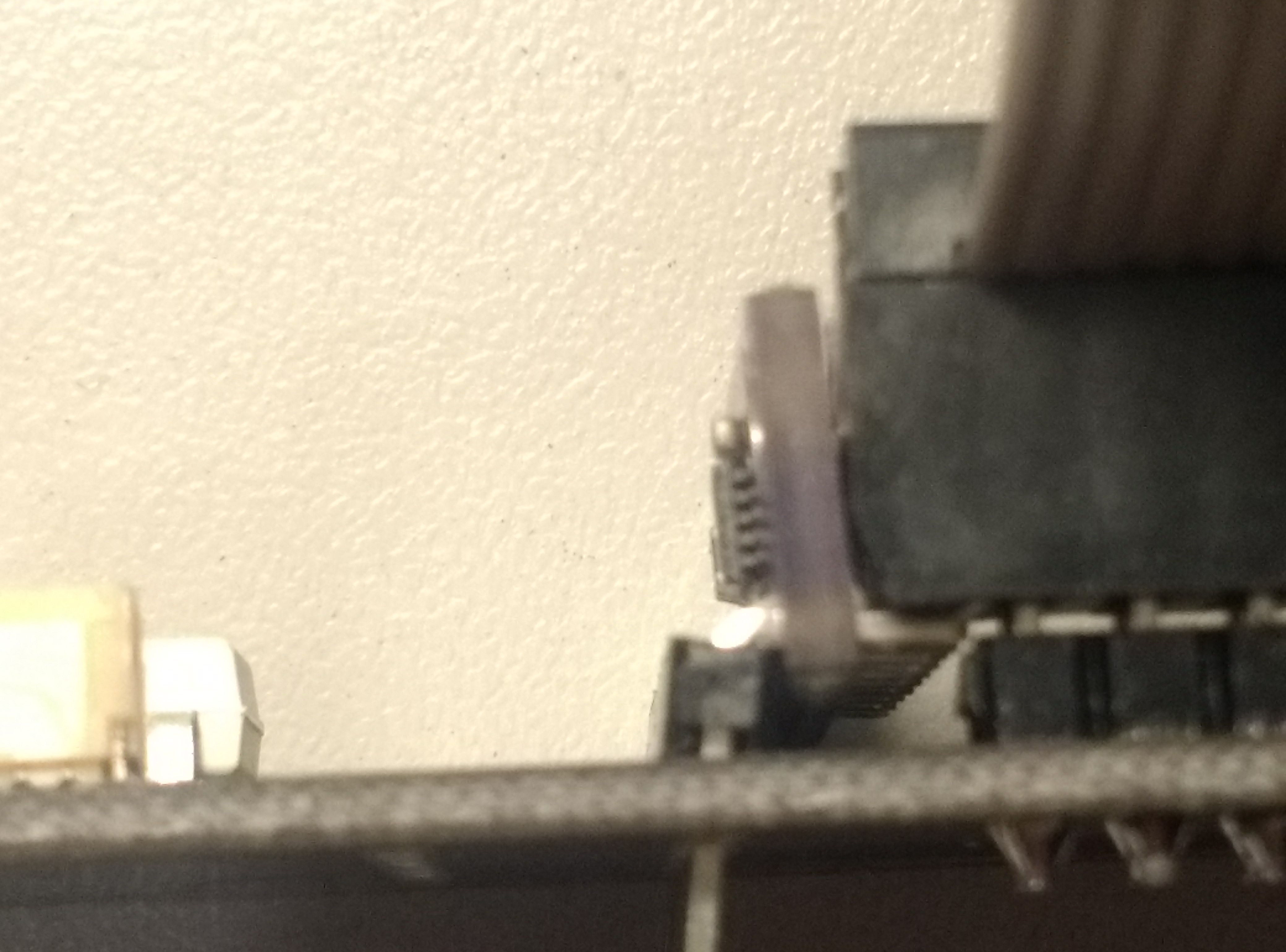
Mounting the 90 degree header with the module as you show fouls the 40 pin connector to RPi. The pins from the child board stick into the space that the IDC connector occupies. I won’t solder anything until you confirm best practice. The only way I can find to get both child modules mounted is underneath like I showed.
I certainly have dusty / oily / generally dirty ribbon cables in the garage which I will dig out for this. I may even give them a wipe over with a damp rag! Spruce them up for their seasonal return to favour.
Regarding docs - I can write stuff in the wiki now that you have clarified the pinout.
See how the IDC connector hits the pins of the 90 degree header pins. The 90 degree pins contact the 40 pin header pins. The 40 pin IDC connector pushes the module. It just doesn’t quite fit.
[Edit] I guess I could trim the pins on the child modules. It wouldn’t be ideal because there isn’t really room to allow the necessary through pins. It might just work but not for the faint hearted! It would be good to see one fully constructed. If that hasn’t been done then I will continue to try to devise a solution.
[Edit] Ah! Putting the child boards on the other side of the 90 degree headers and cutting the pins down might work. The MPC4728 ends up very close to the opto but I think it might work. @jofemodo let me know if there is a way to construct this without cutting pins. Like this:
I wrote my last edit at 00:46 this morning but it didn’t save until just now. I will build it the way of my last picture with the modules mounted on the opto-coupler side of the 90 degree headers, soldered directly to the board but first… That orientation of the child modules places them precariously close to the jumpers on the screen so need to check clearance.
[Update] There is just enough clearance above vertically mounted Zynaptik Expander modules and jumpers on the screen. I will solder this up and write up a guide.
I will let you know how well it works when I have the Zynthian running. I will add construction details to the wiki soon.
Be aware that this kit is recommended for intermediate of better skilled hobbyists. Installation requires soldering 60 closely packed contacts and close trimming of thick pins that require side cutters and a degree of skill. It isn’t very complex but I would not recommend this to a novice.
Wiki page updated with installation instructions. Please check for errors and validity. (I am a pretty good engineer and software coder but my wiki editing skills are… fledgling!)
That was a good idea to mention the different width sockets in your Wiki instructions - I imagine many might not know that and order the wide ones by mistake.


 .
.