I have been working on my Zynthian build for few months. It is very minimalistic approach of V4 version that should be cheap and easy to assemble but still covering most of V4 capabilities including upgraded 5" screen. So I thought to share it to see if there is interest to develop it further or simple to close the project because I get what I needed.
I am sharing it inside designated topic because I believe that this build could be alternative minimalistic approach to build zynthian for people that know how to solder simple through hole components (no difficult SMD components) or have a friend who know it so that they get experimenting with zynthian with the much lower entry cost.
This is not another professional build as V5 or V4 are. It is lucking capabilities such as audio-in, TRS audio connectors, does not come with the best in class DAC for audio out, does not have rigid metal case neither it is 100% tested (it is only me that tested what it by using my workflow).
Main features of this build are:
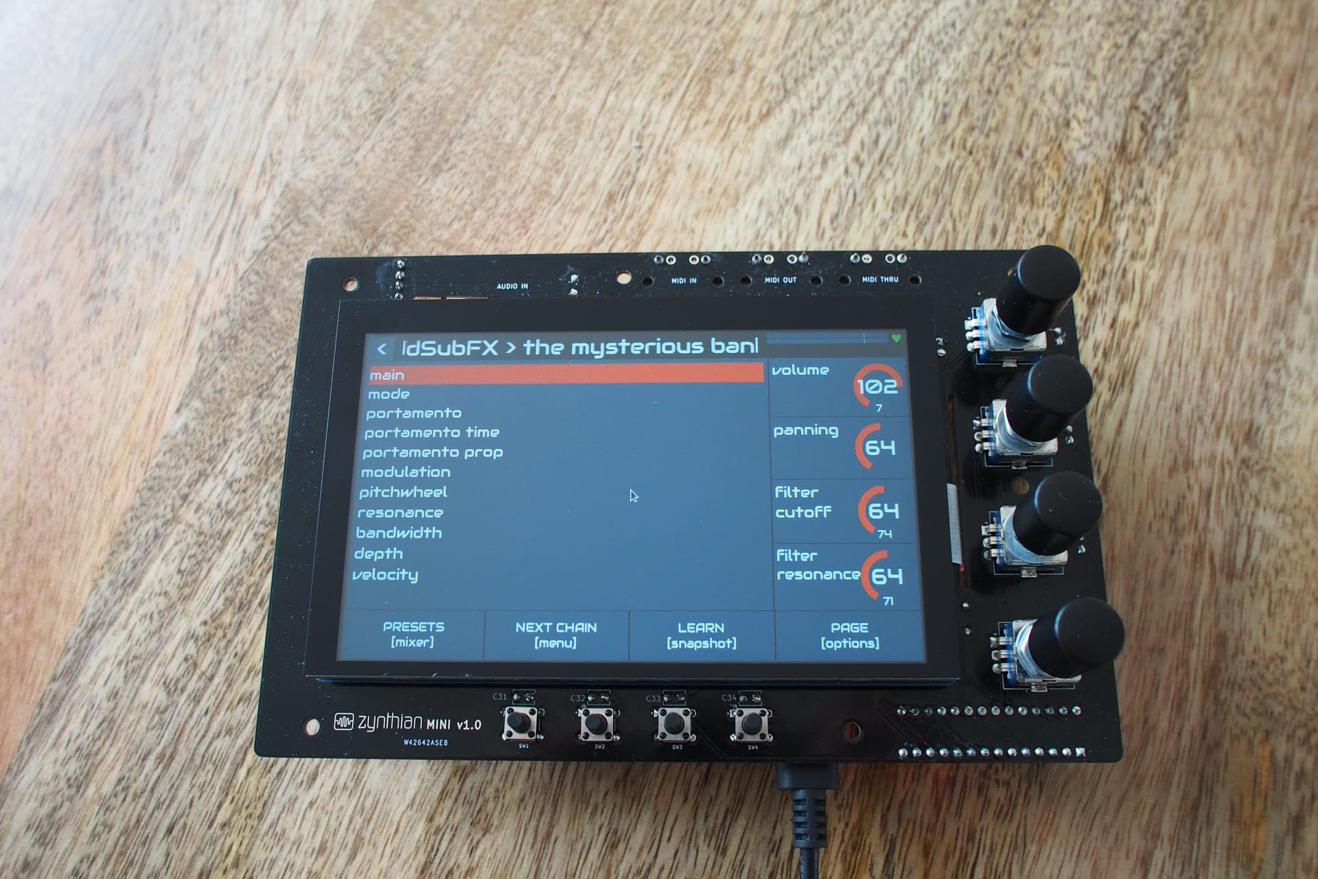
all encoders and switches that exist on V4 version
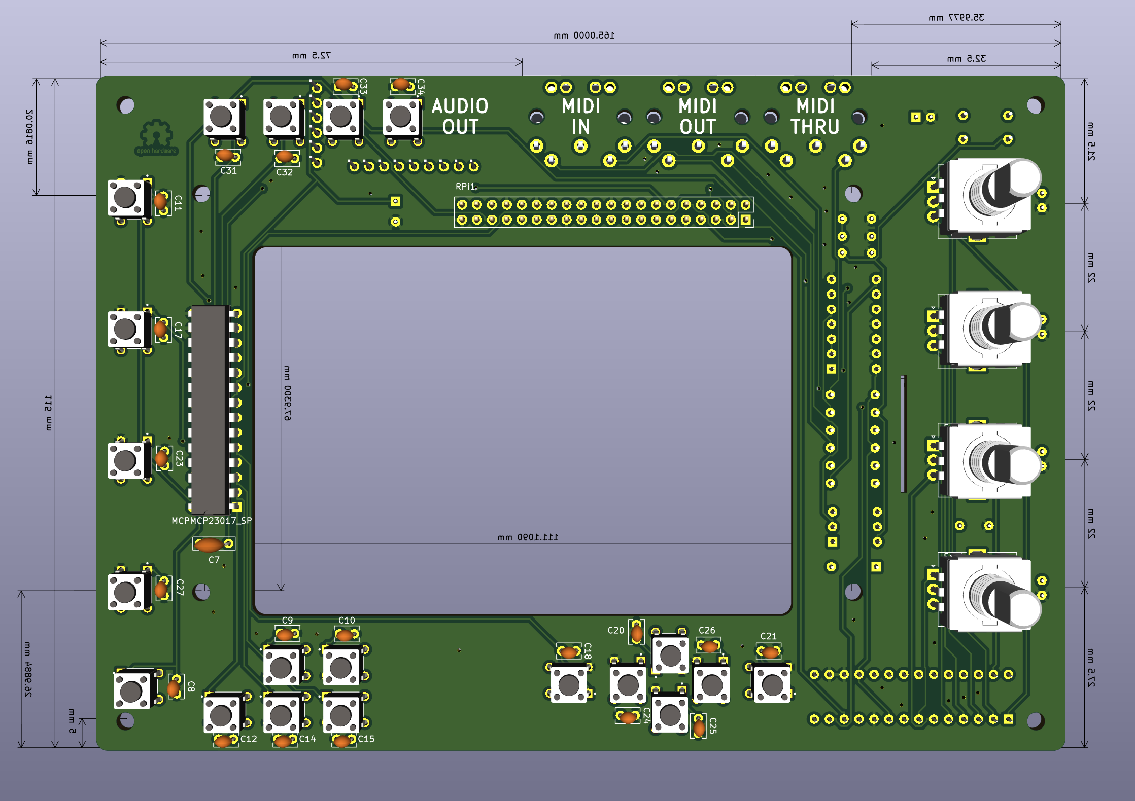
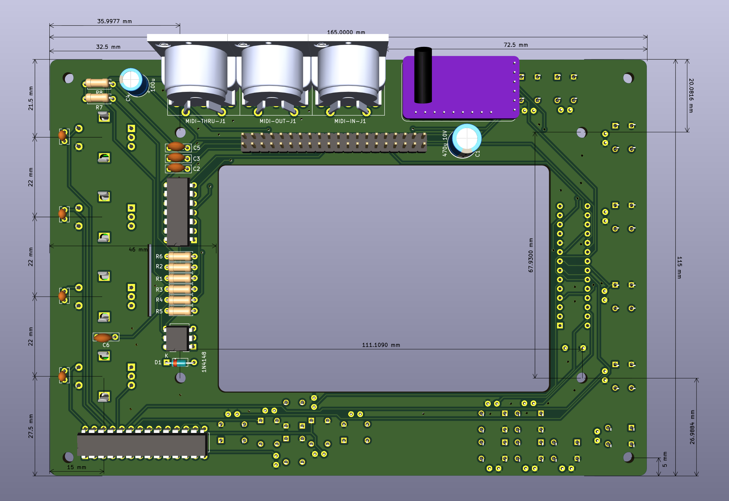
MIDI IN, OUT and THRU
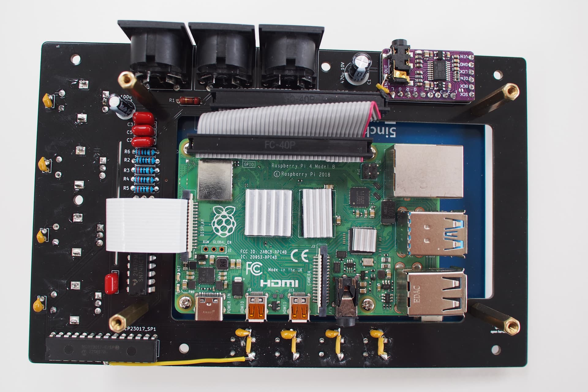
AUDIO OUT (PMC5102 DAC)
no cables apart form very short 40 ribbon cable to connect to rpi. What I have learned is that cables create to much possibilities for errors and random problems due to their poor connectivity when not professionally assembled
does not need the case to start with
most of connectors are easy to reach
Please let me know if there is an interest to continue with this project and maybe become official zynthian mini project that is shared on zyntian githib. We could easily extend this design to:
add audio-in (PCM1805 ADC with similar cost to PCM5102 DAC - 2 pounds)
add one more MCP23017 and get all controls that V5 has (get additional 16 switches and position them on left and some on the top)
add 1/4 stereo jack for more rigid audio connection instead of using PCM5102 mini stereo connector that comes with it
I have also done some estimates and it would be economical for me to sell PCB, 5" screen, all components and short ribbon cable for 100£ so that one would only need to solder components and get rpi to plug in to get it playing. It is only economical for me if there will be 5 or more orders - hence I need to check here if there is any interest for it before I invest in ordering screen, PCB and all components.
Finally here is how it looks now. Please ignore some of the soldered wires they are there due to PCB design errors in regards of 4 bottom switches that I have now fixed.
If there is any interest I have left 4 of this beta PCBs that I would sell for 10£ each. Have in mind that you would still need to do the same re-wire fix which I would explain to buyer how to do it.
I have created wiki for zynthian mini assembling instructions and details for all components and how to get them. It is here: Home · sstojos/zynthian-mini Wiki · GitHub
Hi Stojos, a very great project! I’m interested to build one of it and I hope that you continue to develop it.
About you 3 suggestions for improve the project I agree with you: more I/O, more switches and 1/4 stereo jacks are fine.
I suggest for the next revision of PCB to put the four function buttons under the four functions area on the display, just to have a better ergonomic position.
I hope to see soon more news and improvements from you!
I would suggest putting them on the left of the display and spacing them to occupy the bottom 4/5 so that they align with the corresponding V5 buttons. In this way, if we introduce context relevant screen UI for these buttons, yours will also align.
All great ideas for button placements. It would be ideal if we can add screen widgets to describe their function. What about having 12 buttons, 4 on the top left for jumping to main screens that are not contextual, and 4 on the left and 4 on the bottom.
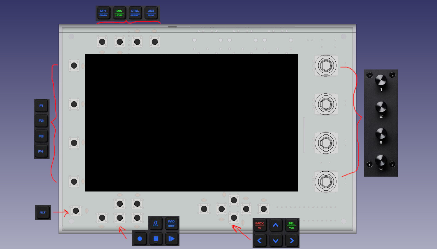
I am just finishing 20 button version. They will not be aligned to any screen widget but grouped similar to v5 version. Top left of the screen will have top 4 buttons of V5, F1 to F4 will be on the left of the screen, bottom of the screen will have one group of 6 for buttons for up, down, left, right, select, and another group of 6 buttons for play, stop, record, tempo, pad and alt. I did this in this way so that config is imidiatwly comparable with v5.
However I like more idea that you recommended. If screen can have contextual widgets aligned to 4 buttons on the left and 4 buttons on the bottom as it already have for encoders on the right.
Let me know if 12 buttons (4 non contextual for main screens and 4 left and 4 bottom that can be contextual ) are too much. I like this idea and I am willing to scrap work on 20 button version and to have this ready today for ordering with pcb way. Also I will send for free assembled PCBs whoever is willing to contribute on screen enhancements for contextual widgets on the left and right.
We do not have any firm plans to implement context labels in the GUI so I can’t offer an (official) advice. We do have the ability to fold in info bars from the top, left, right and bottom and indeed do so for on-screen buttons if enabled in webconf. This does not relate to any physical buttons (which has previously caused confusion).
The V5 has 4 encoders with push switchs on the right. They do not physically align with the on-screen controllers because of erganomics but they are tightly associated with 4 evenly distributed labels on the right. It also has 20 buttons to the left which each has specific functions (with some having alternative an/or context sensitive functions). The layout of these buttons has been carefully considered but is not tied to any on-screen UI, with the exception of the 4 function buttons that are adjacent to the screen because they may be associated with labels in some future (possibly fictional) aspirational development.
The V5 does not have buttons at the bottom but the V4 does. These are effectively the same as the 4 function buttons on the V5 so one might expect that any future association of on-screen widgets may utilise these on the V4 and the side adjacent buttons on the V5.
All buttons are assignable by config (in webconf), even the V5 (apparently) dedicated buttons so you can freely assign functions to whatever buttons you design.
A word of warning about PCB fabrication - there WILL be a mistake! I just got back some boards that I checked and rechecked dozens of times. I found a supply rail reversal on one of the chips. (Stupid kicad library had VCC at the bottom and Gnd at the top of the schematic symbol!!! I mean, who does that???)
I am aware of button configurations but I would like mini to work out of box with default v5 config.
So for now, I will continue with my 20 buttons design so it is aligned to V5 because this will always be configurable out of box. I will make sure that button switches are connected to i/o extenders in the same order and that both I/o extenders addresses are configured the same as for v5 so that v5 config will work out of box. I hope that would be enough.
Is there anywhere svg file for v5 top case design from where I can copy button icons? I could not find it on GitHub. I would like to use them for printing pcb silk screen around buttons.
I will share something tonight when I am back from work to give more details.
I have only beta version left - 4 buttons that need a fix l. Although buttons and encoders are proportionally aligned their positions are all in dimensions with a lot of decimals which is complicating 3d print case design that I am also working on. Hence this pcb will not work for case design.
I can sell it to you but I would advise you to wait little bit more for a new version that I am working on that will have 20 buttons and case design for 3d printing.
Also I have started to work on case design in FreeCAD.
You can find all this inside zythian mini github branch called v2-20-buttons.
I still have not finished 3d case neither I think that this is PCB version that is final. I am looking to not attach rpi to screen screws and instead attach it to PCB . In this case we would not need a cable and we would be able to align rpi to the edge of the PCB so that all rpi connectors are available on the case. This PCB above still is based on rpi being attached to 5" screen screws.
If you consider how your hands will move around when using the device, I think this approach makes for a lot of jumping. I imagine the directional keys and the rotary encoders are likely the most frequently used buttons on the device. Hands will be bunched up close when laid out this way.
Something more grouped like v5 would work better IMO. I think this process will show how much thought was put into v5 layout. It’s (deceptively?) simple with left hand having easy access to buttons and right hand encoders.
How about the F1-4 keys left of screen (for potential future context menus), encoders right then a cluster of buttons similar to V5 to the left side (of the function buttons)?
Problem with any cluster of buttons is that we will need a bigger pcb and case to accommodate it. Bigger case add complexity in 3d printing as most of home printers do not have such a big print bed. Bigger PCB increase the cost of production.
It will be impossible for “mini” to be as functional as v5. Something need to be sacrificed.
It would be good to know what of 20 buttons on v5 users use the most. This layout was just my guess. For example I guessed that functionality of arrow keys and select/back buttons are often available on encoders switched too so I have put them close to encoders.
Maybe we should just have 4 buttons on the left side of the screen and not complicate further - I don’t know.
One thing I forgot to mention, why not consider laser cutting the case? It means it will require a kind of planar design but it opens up different dimension possibilities. You can find nice laser cutter timber veneers online, would be a nice contrast to plastic.
Laser cutters are less common to have than 3d printers as a hobby mashine at home due to their fire hazard and dangerous fumes.
So most of us would need to pay for laser cutting. Probably it would be cheaper to order PCB to be cut and properly labelled using silk screen with no etching at all than to pay for cutting and engraving veneer or acrylic.
Attached link is showing case that is difficult to build because it require delicate gluing of case sides… That is the reason why it look nice. There are other ways of assembling different sides that are cut by laser and easier to assemble but they do not look as nice.
We can print most of 3d case in one go and then just print the bottom to close it. Also with 3d print you don’t have any assembling screws visible. The only problem is that if you want to not look plastic you will need to sand it and paint it.