I have access to a maker workshop with laser cutter so I’d be happy to try designing a case and prototype it. Would you be willing to make a Zynthian mini B (laser cutter version) for this case (a longer one with the grouped buttons)?
If it’s successful, I can share the files for cutting.
I found this place for low volume laser cutting. People can also search in their city to see if they have maker workshops which can be reasonably priced for laser cutting (or 3d printing for that matter).
Great, let have both version available, for people that have 3d printers and for people that have access to laser cutter.
I like laser cutter approach because it is quicker to produce. Also it will look very retro. 3d rinting the case takes around 3 hours.
Let me first finish 3d printing version. Then it will be super easy to change to longer version.
My outstanding tasks on current PCB will benefit both versions. They are to bring raspberry pi close to right edge where encoders are. To do this, rpi will need to be mounted on the PCB instead on screen screws. Also it will be rotated top down so that it can be connected directly to PCB. In this case rpi USB and network connectors will be accessible at the right edge of the device bellow encoders. Also SD card will be easily accessible from the bottom. Finally I will add power connector on pcb so that it is also located at the edge. I can’t move both important rpi edges to pcb edges so I will sacrifice usb-c and video connectors because we have screen and we will have another connector to power so these are not that important.
In regadrs of cooling, yes there is part of screen also covering this hole but not fully - hence I am worried too.
In regards of ADC yes, this is tha ADC that I thought about adding to PCB . I have not yet tried it. There are several challengis to do this quickly. First we need to make sure that both (existing DAC and this new ADC) are working as i2s slaves to rpi sync clock. Then we need to find out if there is a driver out of box that can support both and if not deveop one ourself. For now I recommend to use USB audio interface for audio in until we get start working on this.
The reason why I am worried for coolign is becasue I have build zynthian before with rpi DAC HATs on top of them. In this case I often see thermometer icon on to right corner of the zynthian screen which, I believe, means that rpi is slowing down CPU to manage temperature. I did not have any performance side effects but I do not run complex setup with multiple layers playing at the same time. I would rather to not have this alarms.
You should definitely avoid the over-temperature alert. Not only does the CPU throttle but there is increased risk of damaging the SoC or other components.
With this kind of passive cooling on the Pi4b and even in open air, I had many throttles under heavy load with Zynthian.
So regarding your PCB design, I suggest:
mounting the Pi upside down (it will need additional 40 ribbon cable + connectors) so that the passive heatsink touch the bottom plate “a la Zynthian V5 kit”
break out somewhere on the board a pin header footprint for BCK, LRCK, DIN, 5V, 3.3V and GND
I am trying to not depend on metal case option - even if it is just a bottom part it is too complex for home build. Probably it will need to be active cooling. This rpi 5 cooling HAT will work even with current rpi orientation.
It will push rpi connectors more towards the bottom of the case which is not bad because they are too high at the moment.
I think that we should brake out the whole 40pin connector and holes for mounting screws so that custom hats can be added. Preferably on another side of the PCB so that HAT connectors are available on another side. It will be hard to route all connections. Let see what Freerouting will do.
Hello stojos, great work! For information, I use the same type of cooler for the RPI processor, I had to adjust it with a file tool so that the IDC plug fits into the GPIO socket.
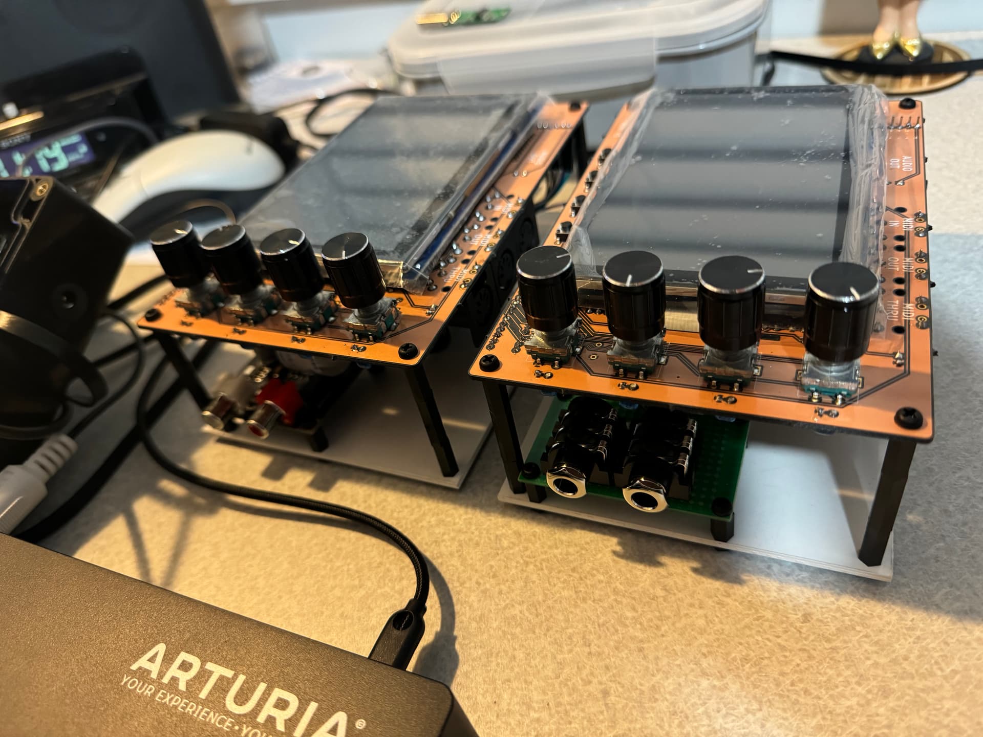
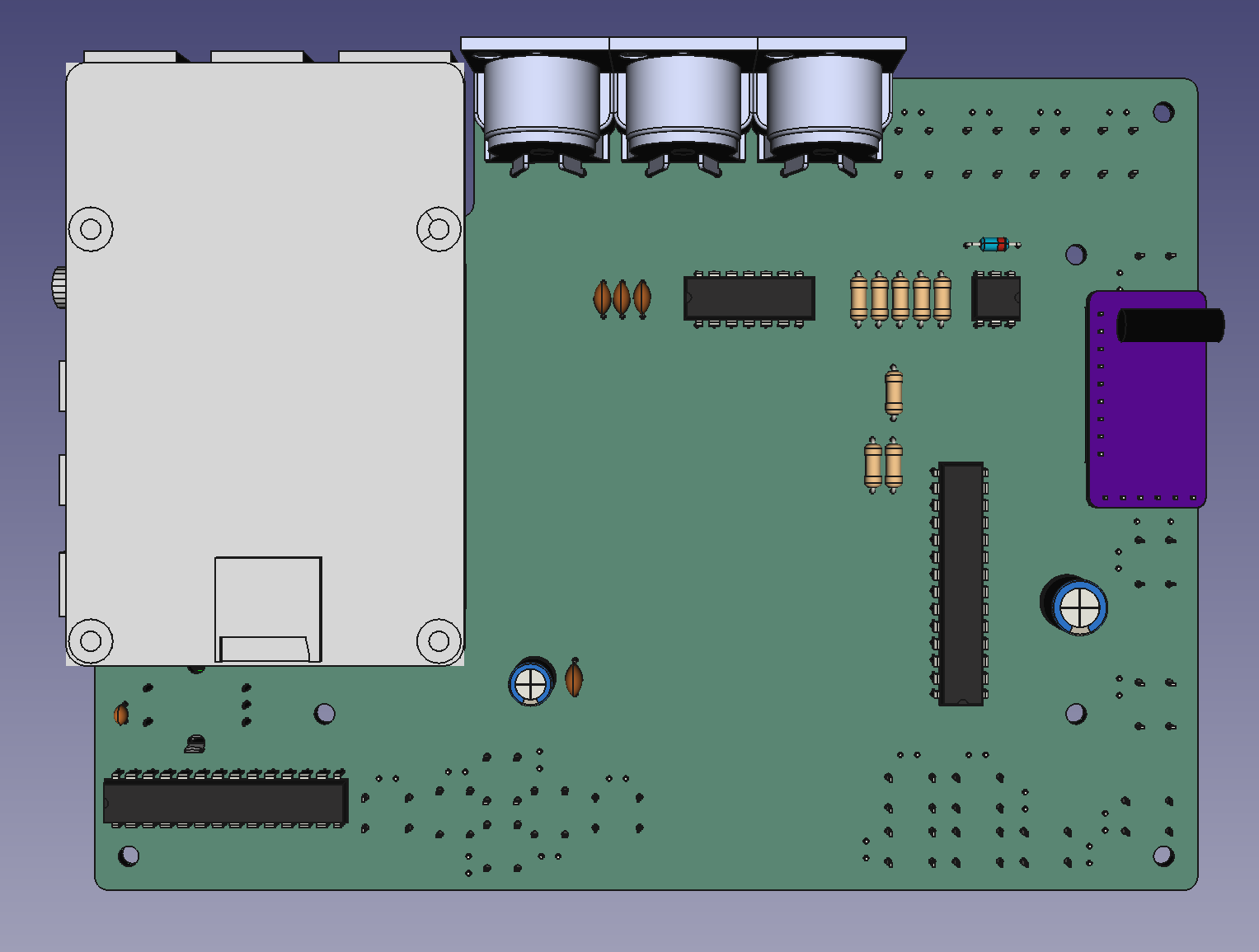
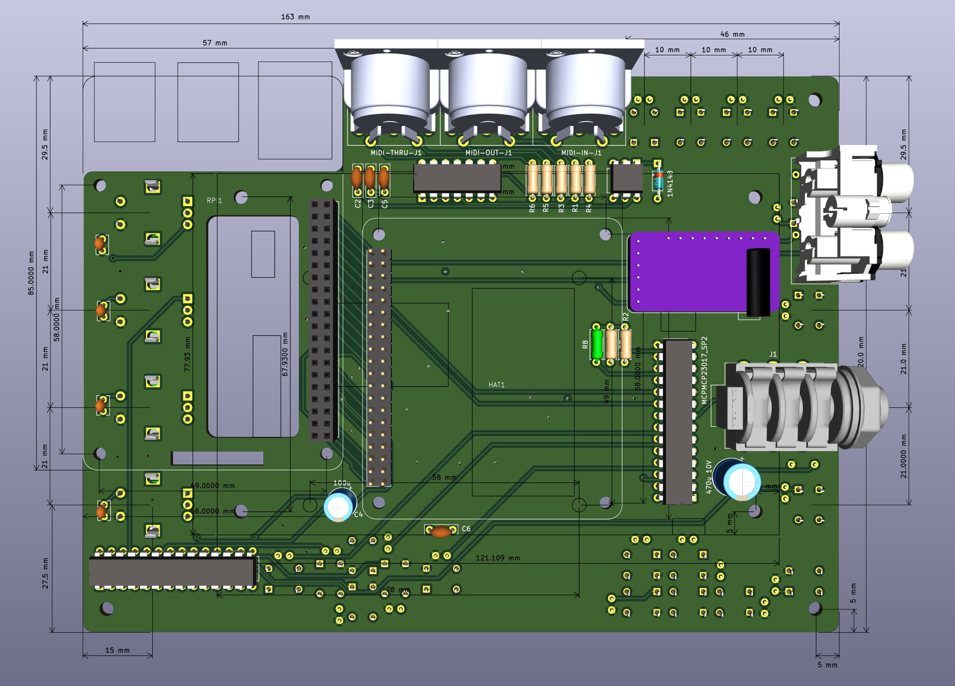
I have just now finished and send for production new v2 20 buttons PCB version. It now includes two audio out connectors (RCA and 1/4 stereo Neutrik type connectors) so that you can choose one that best suit your to solder. It also include additional 40 pin header connector and holes for stands for any rpi HAT (e.g. if you want to use your own audio HAT instead of cost effective one that must be soldered on the board - in purple ).
This is still inside v2-20-buttons branch on github. Once I receive PCBs and successfully test it I will merge it back to main.
If this works well I will add another longer PCB layout that will have all 20 buttons arranged in the same way as in v5. I did not prioritize this because that PCB will be more expensive and I would not be able to 3D print the case for it because it will be to long to fit onto my neptun 4 printer bad.
Finally github branch also include case design in Freecad file format for this version. I will test that too.