Sort of Rypdal-ish, isn’t it? ![]()
I have built another zynthian mini today to pair with my new akai apc key 25.
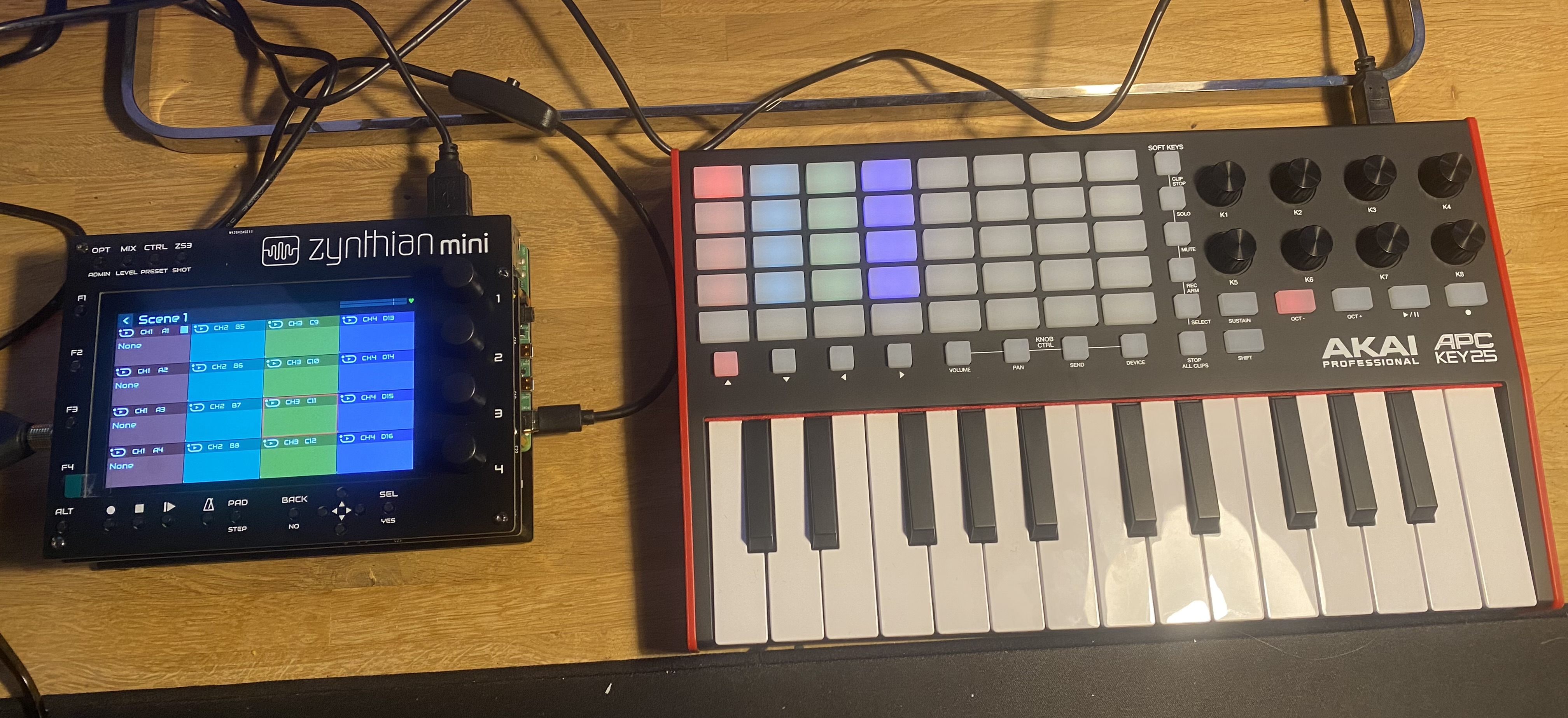
It went smoothly and everything worked on the first boot of latest stable oram. It takes around 3-4 hours of careful soldering and assembling.
I went through docs of zynthian’s akai apc key 25 driver and what a great driver this is. Thank you @oscaracena for building it.
8 Likes
Thanks for your encouraging words! ![]()
![]()
2 Likes
Sorry, can’t find any information but will there be a complete kit for the Zynthian Mini to purchase? It seems to be a beautiful device.
EDIT: Ah. I see there is a complete guide in Wiki to build by yourself. Thanks.
It seems unlikely, and would probably cost. If you wanted to put together a group buy of PCB’s that might be the best bet of a way to get it. You could probably also ask if anyone has any extra PCB’s or components they might part with, but sourcing the components you actually need is pretty easy and cheap.
1 Like
Current zynthian MINI is designed for people who can follow instructions available on zynhtian wiki. In nutshell for people that know how to solder components on PCBs that can be ordered directly from china here:
This PCB is using through hole components for easy soldering by humans so can not be soldered by robots in factory. I have designed but not tested yet PCB that uses SMD components that can be placed by robots on top of PCB and soldered directly in factory oven. I am still investigating if there will be enough interest for already assembled board in factory knowing that cost will be close to V5 main board. There are some benefits of this approach compared to V5 main board because you can use single MINI V2 board and have mostly everything that you need without a case. It will keep together rpi, screen and have encoeders and switches. Also case can be printed (design is also available). I could add audio in out and headphones from V5 to such design but probably would need to remove HUT in this case so I am investigating another option with just audio in board as it is currently designed for audio out ad keep the HUT if somebody would like to slot in hifiberry card instead of cheaper cards.
The problem with this approach is that it would be too expensive for people that just need one assembled bord to order themself directly from factory. Minimum orders are 5.
I could fund ordering myself and then reselling individual boards but this would require additional administration on my side (open a web site and managing this additional income and tax). Finally, @jofemodo mentioned to me before that he is planning to design something similar to MINI and have it on zynthian store. Hence I am worried that my approach would be just waste of my money.
2 Likes
I will add that I’d probably be willing to put together a group buy in a couple of weeks if there’s an interest. My day job is industrial controls so I am pretty regularly ordering boards from PCBWay anyway, and would be more than happy to add a few sets of main PCB’s and fascia’s to my order for resale. I’d point out that I would have to add a share of the import costs to the US as well as charge a small amount for shipping them back out again… and I’d realistically only be able to do this for North America (US and Canada).
I’m running inventory next week of boards to see how many I need to order so I’m probably placing an order toward the end of the month. I’ll have to do some math and see what the resale cost is going to realistically be.
3 Likes
@riban asked me again to rethink about creating mini euro rack option. I am evaluating this option - hence looking to first 3d print rack itself based on @infinitymodular design.
In regards of mini euro rack version - what I need help with is the position of rpi and connectors. At the moment they are aligned to the edge of PCB - but PCB will be inside the rack and hence not that accessible anymore.
MIDI and Audio connectors already have additional pinheader connectors on PCB so that equivalent panel mount connectors can be used and by cable connected to PCB . These panel connectors can be mounted to additional euro rack facia that can be positioned left or right from main zynthian facia.
However I need advise how to position rpi. Should I leave it as it is or move more inside so that there are more space for connecting USB cables and power to it ? Do not expect the rpi to be right in the centre - there is already additional HAT there - rpi will probably be just more inside so that when cables are attached they do not go out of PCB area.
Also I will improve existing buttons with better one that have caps that are 7mm wide but with the same footprint. For arrow keys and OK button I am looking to incorporate this if 7mm is too big to use
I mentioned 3U or Eurorack enclosure because it had already been suggested here and others are intereseted in the form factor. It seems to make sense that, if zynthian mini can be made to fit within a eurorack format then there would be good advantage. Those who want eurorack can take advantage of the format and those that don’t can simply mount it in their own enclosure.
A few challenges with eurorack format are:
- Connectors
- Cooling
- Power
- Size constraints
Connectors
RPI has connectors on several edges. Zynthian tries to expose several of those directly and extends some using cables or PCB. Zynthian mini may wish to do similar. It may be acceptable to reduce the quantity of exposed connectors, e.g. fewer USB outlets. Connectors could be on headers or via direct cables and allow builder to present on a separate panel, e.g. if a user wants 2 USB, MIDI and 1 HDMI then they could build a eurorack panel with these connectors, each with cables to the mini.
Cooling
Eurorack tend to be fully enclosed (although that is at the option of the user who purchases or builds the enclosure). The enclosure may be of varied design so there is no standard for distance to the edge and hence it may be challenging to use the enclosure itself for heat disipation. It may be advantageous to provide vents and/or heatsink on the front panel (or adjacent).
Power
Most eurorack enclosures have some form of power distribution that is aimed at analogue audio modules. They seldom have sufficient 5V power supply to support a RPi5. Also, the PSU may present on a connector that is not suitable for zynthian mini. We could place a suitable / common connector on the PCB to allow powering from a typical eurorack PSU. It may be advantageous to expose a power connector on the front panel to allow external supply.
Size constraints
This is simply recognition that designing for a predefined size and shape of enclosure places restricitions on the format of the product. One aspect that should be considered is depth. There is no real standard for how deep enclosures are. I try to design for the shallowest, like the Behringer which has just 38mm depth but that is rather challenging.
Try very hard to get the USB & Ethernet connections on an accessible edge. It is amazing how much space USB & Ethernet connectors and extensions take up. Also make sure you can easily change the SSD dsk I’ve built machines where this fairly rare evnt is an absolute nightmare.
Within a case you can supply power (+5V) directly to the GPIO connector thus saving space around those connectors. Will you make the hdmi connectors available?
I also make sure that all wires leading to the PI are removable in some way. Again the sucsession of rebuilds involved as kit comes together seems to throw up endless issues and one good idea bumping into another.
If you can get the design into 3D software as early as possible that would surelyy help, but I haven’t done this as yet, primarily cos I’ve not got a 3D printer so I’m not forced down that route and I’m unsure which is a good 3D software to use.
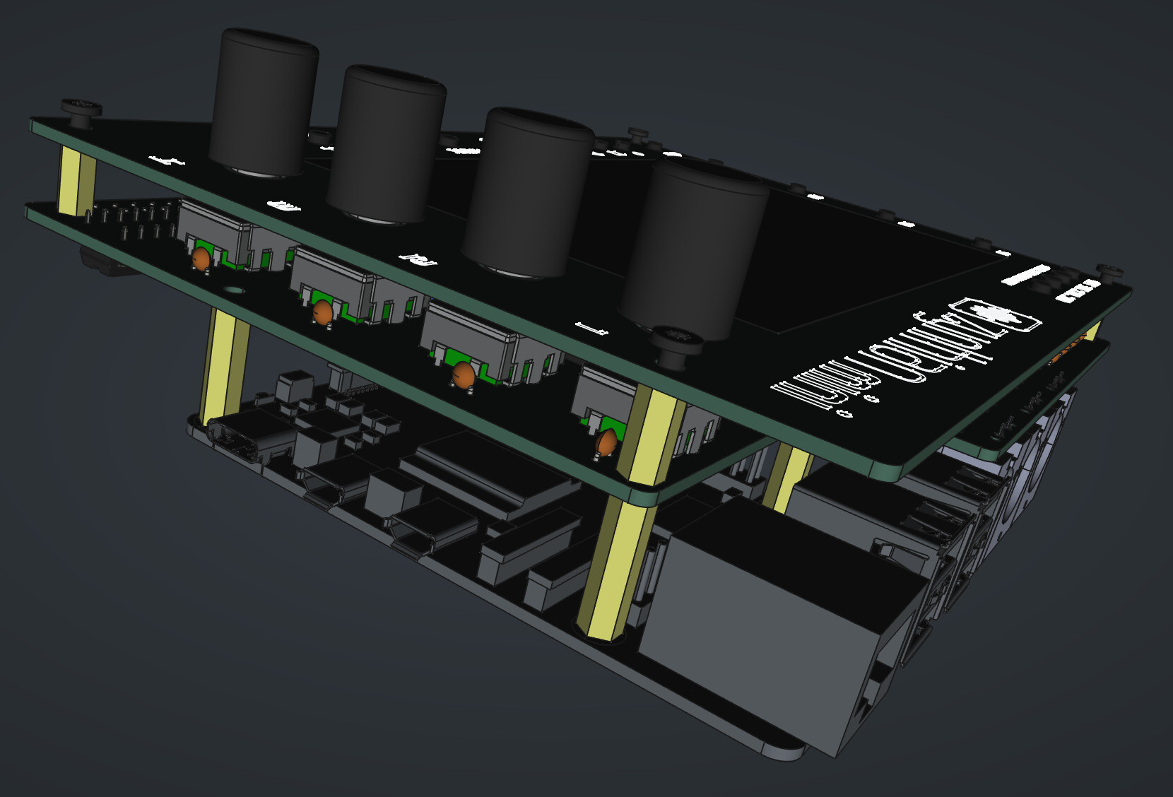
Thanks @wyleu for advise. I do put all my designs first into CAD software too see how they fit together so I will share initial designs screen shots here for further discussions and suggestions.
I will just position rpi in the same way as now apart from it will be more inside so that when cable is plugged to them cable connector is not getting out facia boundaries.
Current position of rpi allow active cooling to be installed. I prefer to use 40pin connector with at least 2 spacers so that distance between rpi and pcb is 16mm which is enough to air flow around. Sometimes I use 3 spacers so that there is even more air but I don’t see difference. Active cooling is totally fine with rpi5. Fan is automatically controlled by rpi and rarely switched on - only while playing some demanding synthesis or aida-x with vnc enabled when cpu is 100%.
Where can I found a common power connector footprint ?
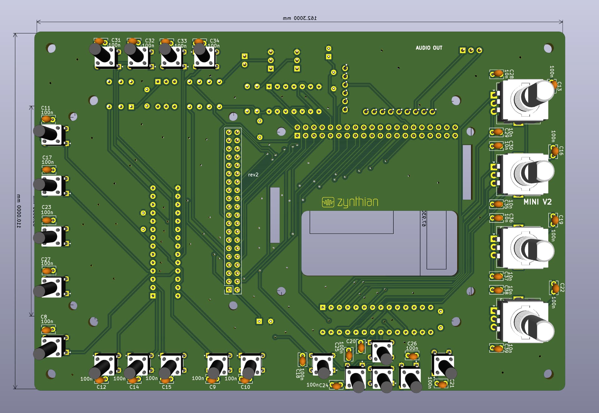
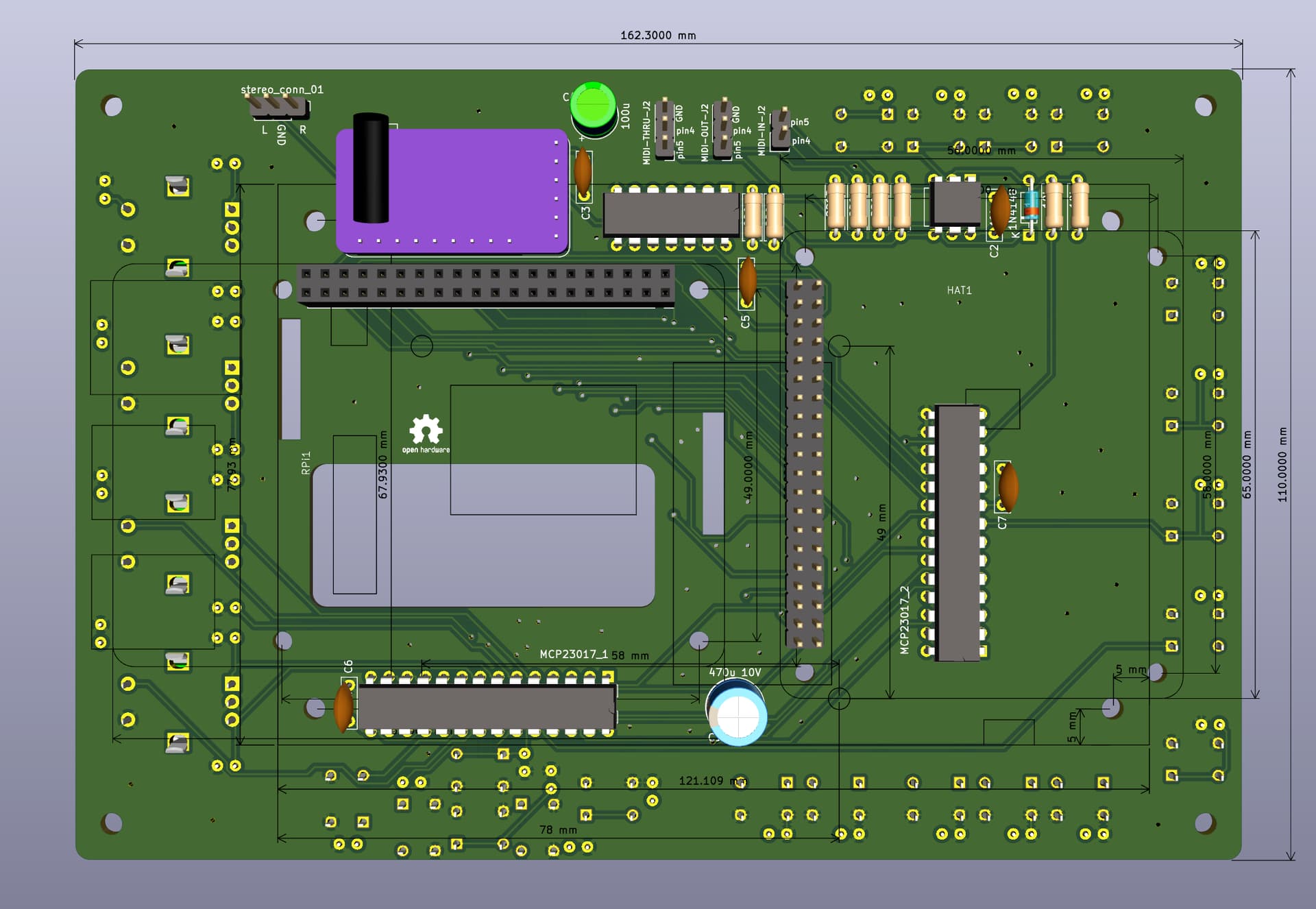
38mm deep would not be to hard to achieve. PCB is 11.6 mm away from top of the screen, so if you include pcb thickness 1.6mm, 16mm spacer for rpi and rpi board thickness you end up with 11.6+1.6+16+1.6=30.8
1 Like
This image is from Division 6 website.
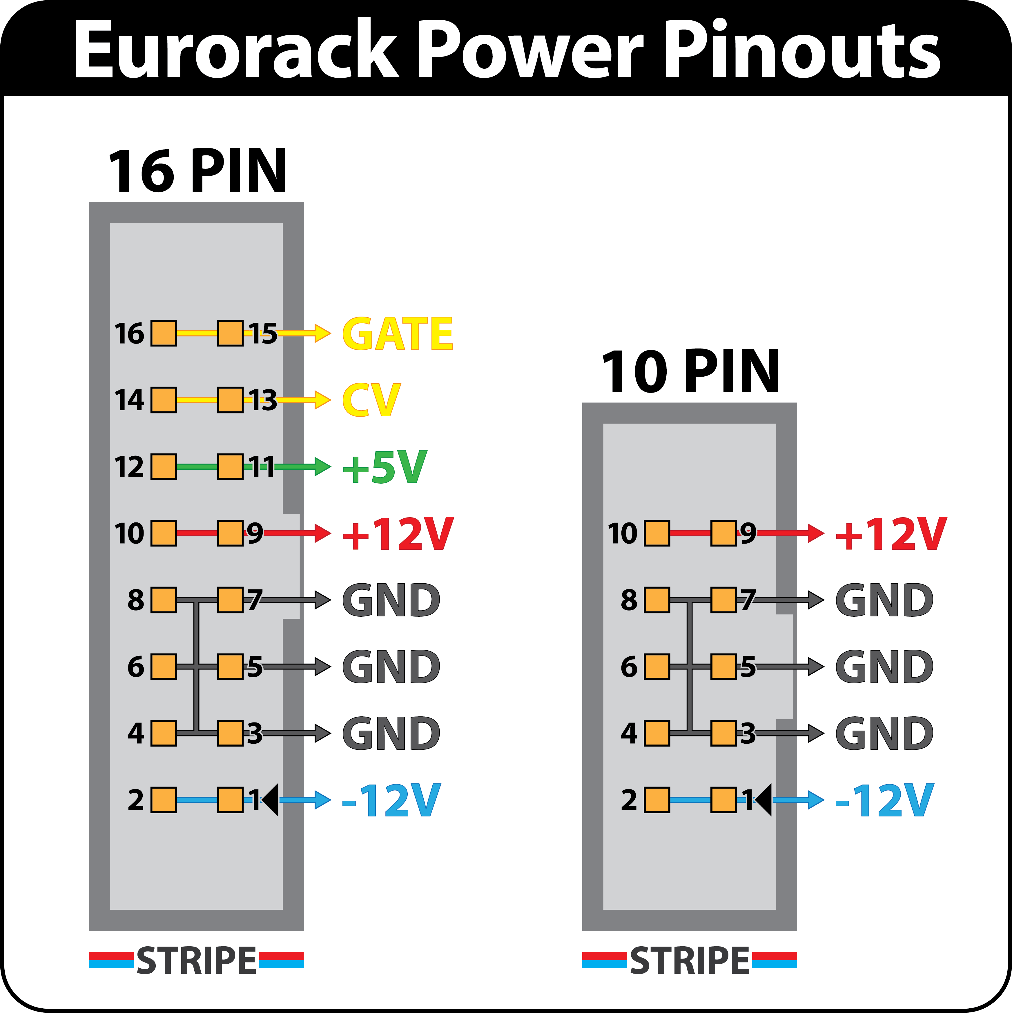
I beleive this is fairly standard pinout, using a DIL header. Many eurorack PSU present on a bus with multiple sockets that are then connected to modules via flying cables in a star. This would mean that a user could actually make their own cable with header on one end and any other connector soldered to the other but that is possibly more challenging for some users than using an off-the-shelf ribbon cable.
The 3D render shows the RPi very close to the top edge of the front panel. For a eurorack module you need to have certain clearances to allow the module to fit into the rack between the rails. You also want further clearance to make connections to the sockets. So I would imagine the RPI being oriented closer to the bottom of the panel or rotated 180°.
PEZ
None of the current crop of eurorack modules offer a dispenser for PEZ candy. This is a huge oversight.
This screenshot is from existing mini design, not a eurorack mini design. It was presented to show a depth of all component included and not position of rpi. Depth will not change and will stay just above 30mm.
I will have a first draft of eurorack component location soon to share.
1 Like
Euro-rack is great for mini version design.as i decide to take my own design in XENT project(longtern),i had find something,i think it have something that we had to take attention:1、if the power is from DCDC 12Vto5V or directly form 5V? if from 5V,i think should consider if the power supplies of mainstream Eurorack solutions drive it? 2、what about a pannel with interface?there lots of type of interface,i had take look at zynface i think some of design not totally fit for People who frequently use Eurorack.
Perhaps a modular hardware approach? The eurorack zynthian is a highly specific use case?
This is music tech. It’s mostly about connectors & If it can go wrong it will go wrong. Expect every possible misuse ( reverse voltages, badly assembled equipment, active misuse).
And construct for your particular desires in mind.
I.e What ever you do make sure you put a decent diode on the PS to prevent reverse DC or better still a full bridge rectifier, if you are going into a home constructor environment.
Indeed! I would recommend a (5HP) panel with 3.5mm (1/8" / minijack) sockets to expose CV/Gate. Such a panel could have electronics to protect an condition the signals for presentation to the user / other modules. Similarly there may be a panel that extends less used or custom connectors, like I suggested earlier. So we could present extensions to the core mini via custom panels.
Hi @SinisterCrayon !
I would like to order a couple of PCB’s and facias for this build if you are still ordering from PCBWay.
Here is the first draft of Zyntian Mini v2 Eurorack assembled.
Here is the exports from KiCad:
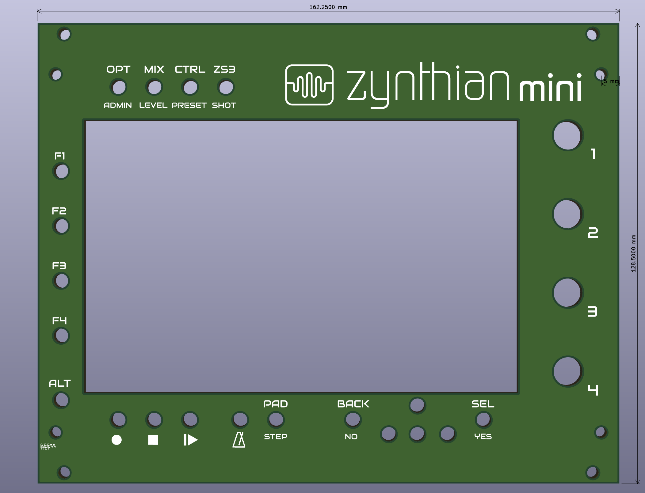
MIDI and audio connectors could be merged into single 12 pin connector that can be with a single cable be connected to 3.5mm female connectors on a separate (5HP) pannel.
What could be interested is to instead of having HAT to have additional 40pin connectgors so that a separate 5HP panel with audio card and separate panel with CV/Gates can be connected. This would also allow space for rpi to be more inside.
Forgot to say that rpi will need to be connected to 40pin female header with 3 spacers so that there is enough space for network and USBs to not touch PCB.
EDIT: all resources (KiCad and FreeCad 3d design) can be found on my (stojos) fork of zynthian-hw project inside the branch MINI_V2_EURORACK. Once we are happy with design I will do pull request.
7 Likes