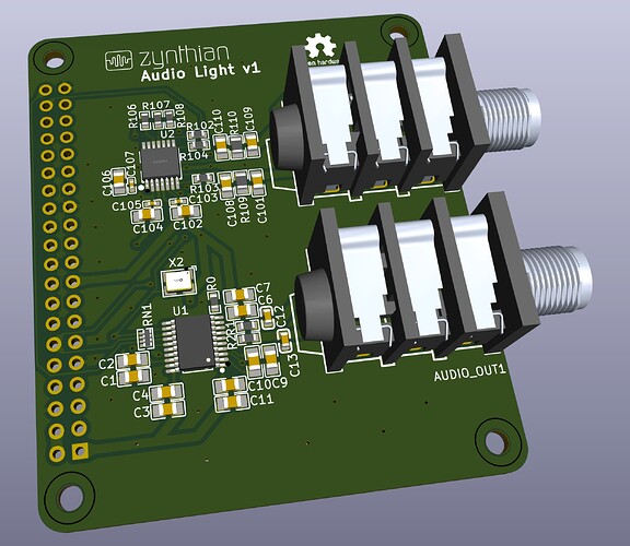
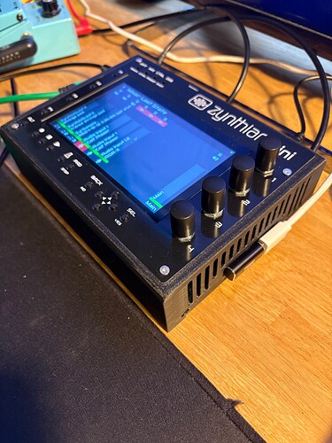
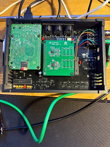
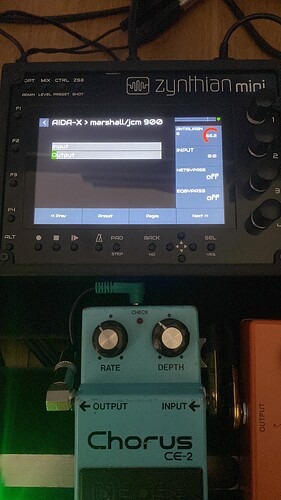
Ooh, it would be cool if it was possible to build a Zynthian with a selection of 8 ins and outs. Could replace a multichannel recorder or maybe even an audio interface
Finally for testing the standalone codec, I’ll go like this:
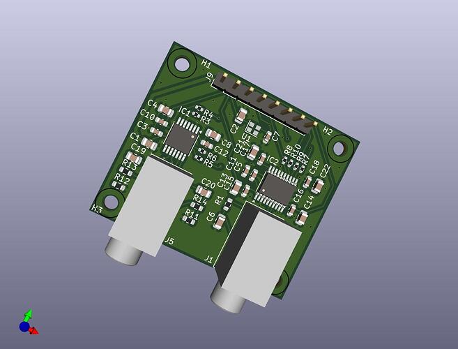
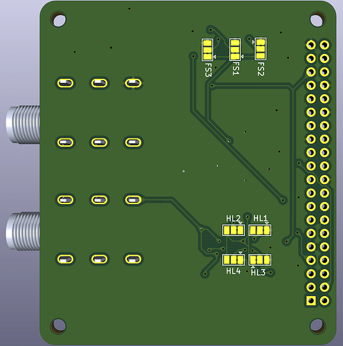
As is,
- it will be less fragile then a 20 mm wide strip when/if shipped to intrepid Zynthianers
- if it works, it can be used as a standalone codec with its mounting holes, and I believe, the format is more flexible (there is only one side with audio connectors, contrary to a “strip” layout where you are stuck in a given format because of the distance between the 2 audio connectors)
- all passive components are basic parts. As extended parts (+3$ fees / part for setup the production line), there are only the 2 PCM chips and the crystal. <=> +9$ for the batch,
- otherwise, for all the parts (without additional setup fees for extended parts) it wil be arond 3,00€, VAT excluded
Some questions:
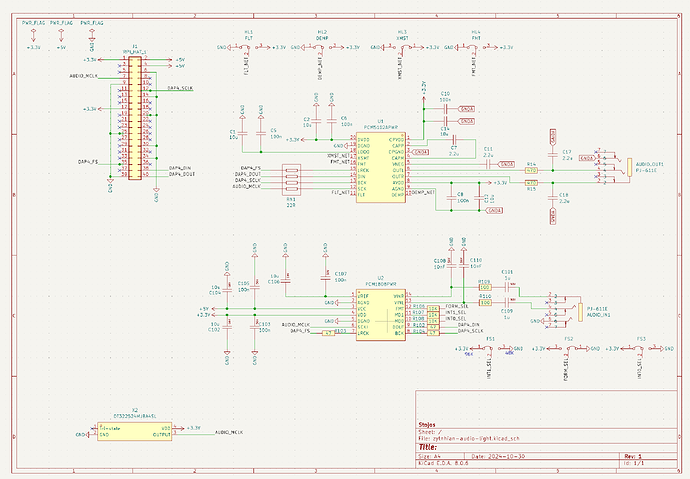
- I’m not really comfident with the crystal I choose. The datasheet.
Should I use 2 15pF capacitors around the crystal ? - are these small resistor (from R3 to R10) really needed in series to all digital lines ?
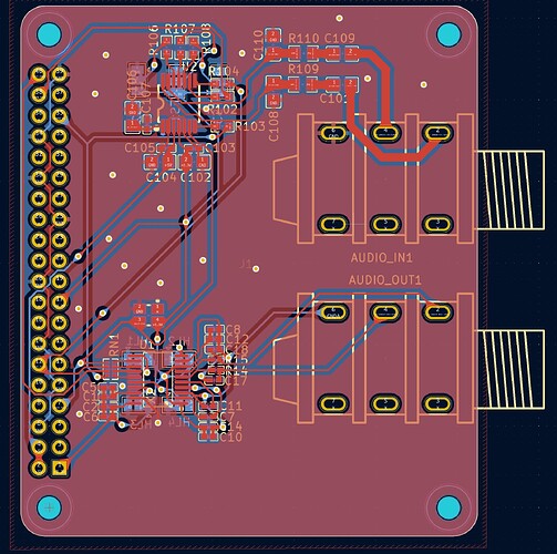
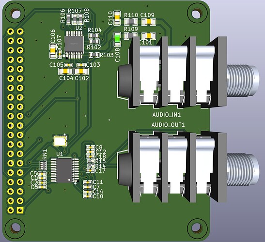
I’m not totaly satisfied with the routing . Especially close to the header: it’s a kind of mess with too much vias imho, and the grounding of the board with only one GND pin header looks to weak. There will be another design iterration …
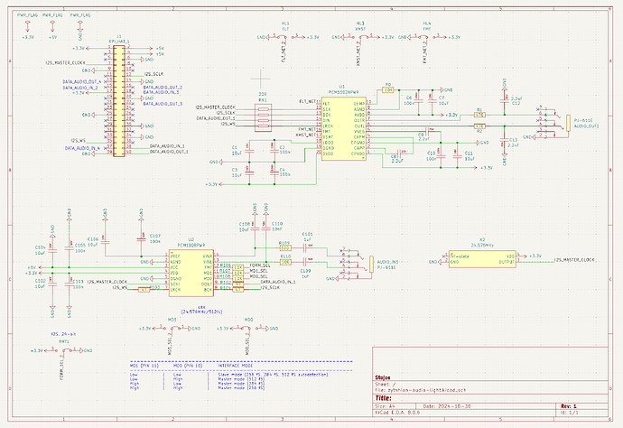
Oh @le51, I am doing the same. I have based schematics for pcm1808 on exact the same prototype board that you shared. At the moment I am finalizing pcm5102 design on prototype board too. I am using lcsc parts and so far all are available in great numbers.
I am trying to do the same routing as it is on prototype board.
It would be better to share schematics when referencing the components. Prototype boards comes with detailed BOM. I am using that.
Here is where I am at the moment.
This is schematics:
PCM1808 is 100% the same as prortotype.
PCM5102 is based on a cheap CY-PCM5102 boards but I am in process in changing it to Texas Instruments prototype.
Oscilator schematics are based on kmwebnet/simplecodec3 but I will change it be the same as TI prototype.
Here is the wiring - (PCM5102 wiring and oscillator will be changed.)
I am using solder jumpers instead of pinheaders - we will probably rarely change them too what they are set by default in schematics.
Forgot to say that all component ids for PCM1808 are increased by 100 to what they are in TI prototype (e.g. C1 is C101) so that we can easily find them in TI schematics and their BoM. When I change PCM5102 to TI prototype schematics I will use the exact IDs.
hey that’s good ! But …
I’m not that fan at all with the “Raspberry Pi Hat concept”: [OFFTOPIC] covering the CPU with it is such a non sense for me … anyway, it’s practical. But what a strange (and strong) design choice. They are only a coulpe of SBCs (Nano Pi M4, Odroid N2, maybe a few others) that have the CPU on the bottom side of the board, wich is much clever imho.
With it’s dimensions (65x56 mm), only one piece fits in the 100x100 JLCPCB standard PCB board. But I do not know if smaller but customized sizes are more expensive or not. [/OFFTOPIC]
Back to the design:
- I agree with the choice of solder jumpers for ICs configuration, there’s no need of DIP switches or pin headers+jumpers for that.
- I too have follow the TI docs for schematic, so both of ours are mostly the same.
- I see you’re distinguishing GND from GRNDA, how do you implement this on the PCB ?
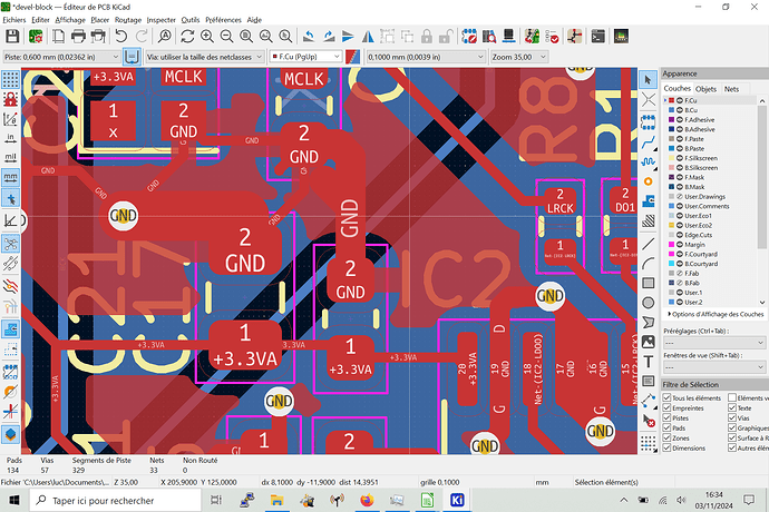
Right now I’m struggling for having wider GND plate around my GND pads (I’m trying to find a way to bypass some Kicad design rules), below an example
I’m trying to have a continuous GND zone wich will cover all the ground pads (I do not want to see that blue underlying color ![]() ) around crystal, capacitors and ICs GND pads.
) around crystal, capacitors and ICs GND pads.
@stojos , here are my kicad projects.
One is “strip”, not that much advanced, because of the other one called “block”, as shown above. For this one, all the parts are sourced/referenced from JLCPCB.
For 20 pieces (= 5 PCB of 4 codecs), parts are around 42€ total + 9€ of additionnal fees for 3 extended parts+ VAT + shipping (and without the two
3.5mm jacks and the pin header)
devel-codec.zip (3.9 MB)
You need to change pad connections from thermal reliefs to solid .
@le51 - your schematics are more similar to kmwebnet/simplecodec3 than to Texas Instruments prototype boards. I will therefore continue to finish design based on Texas Instruments prototype boards and check what is the estimate to build them with jlcpcb
This board is prototype for developing codec and once we have it working we can put into a different design. My idea was to plug prototype board directly on mini’s hat which is a separate from rpi. In this case we don’t need anything else for developing codec.
If you don’t have mini and if you don’t want to put it on top of rpi you still need cable from rpi to board. The only difference is that you will need standard rpi 40pin cable instead of custom 8pin.
Great tip, thank you, that change my life ![]()
Hi !
I guess but I’m not sure : it is rpi5 compatible because there is no obstruction of the ports, or there is an other thing that prevent to use of a rpi5 like… Heat ?
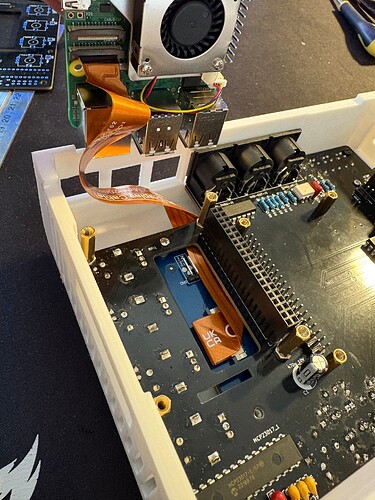
MINI is compatible with rpi5. DSI cable need to be differently routed but it is even more elegant on rpi5 than on rpi4. Here is how cable need to be routed on rpi5:
In regards of heat, it is always good to use female 40pin header with spacers so that there is enough space between rpi and MINI PCB. You can see on photo above that I use here female header with 3 spacers which increased space between rpi and pcb from standard 11mm (with no spacers) to 18.5mm (every spacers is 2.5mm). Female 40pin header with 2 spacers increase size to 16mm. I often use just 2 spacers because it is easy to find 16mm posts. There is no 18.5mm posts but you can easily get 18.5mm height by adding screw nut on top of 16mm post as you can see on the photo above.
I have ordered 10 audio cards from jlcpcb so it will be with me next week. I will send two to @le51 and two to @riban and I will keep two for me. Therefore, there will be 4 left for other people to get if they want to help us in developing codec for this.
If we get codec working we can easily add another 3 PCM1808 and 3 PCM5102 to this design to achieve rpi5 potential of 4 stereo audio inputs plus 4 stereo audio outs. The only difference is that there will be no additional main oscillators and another 3 PCM1808 would be in slave model. My assumption is that there can be only one master that defines BCK and LRCK which in this design is PCM1808.
Oh gosh… Don’t tell me there is a PCB left somewhere in France, I need to control myself and not buy this “just” to see how cool Zynthian can be with an rpi5 and more buttons… ![]()
Great. Thank you.
It hasn’t moved a lot here in that manner, so I will be very happy with your hat.
Hi Stojos
I already built one mini with the facia and love it. Now i wanted to try the 3d printed case but the buttons do not line up in the bottom row. There are 2 rows in the 3d print while on the pcb it is only one row. Where can I find the correct 3d print files?
You can find latest on my fork of zynthian-case project inside MINI_V2 brach GitHub - sstojos/zynthian-case at MINI_V2
Cases are designed in freecad app. You can also use more stable ondsel clone of freecad.
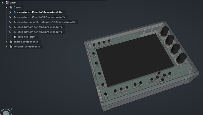
Different case designs for MINI_V2 are inside case.FCStd file. Not all are exported as STLs. If you need something that is not in STL folder select part in free cad file and export as STL.
When you open file in freecad or Ondsel you can see parts on the left. I have case with opening for rpi5 and for different stand offs (deepening if you solder 40pin connector with one or two standoffs rpi5 will have different openings).
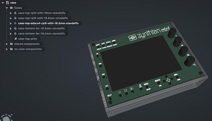
also you have case that is designed to accommodate PCB facia.
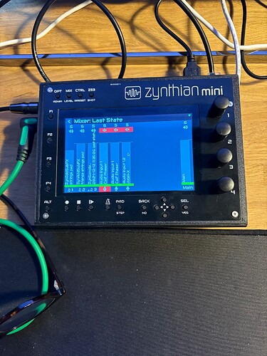
it looks like this when printed
That looks cool,
so it mixes the facia with an enclosure.
So these two should work with a pi 5 and three spacer female 40pin vertical header:
enclosure-rpi5-with-16mm-standoffs.stl
case-bottom-for-16mm-standoffs.stl
enclosure STL files are old PCB facia enclosures which do not look like what I have just shared above. I did print them to test and they are ok but I was not fully happy with design as the one above. Here is how old enclosure looks like when printed:
Design for old enclosure is not available in freecad file anymore but can be traced back on GitHub if you want to customize it future.
