This is a build report, including as-built schematics and a small patch file.
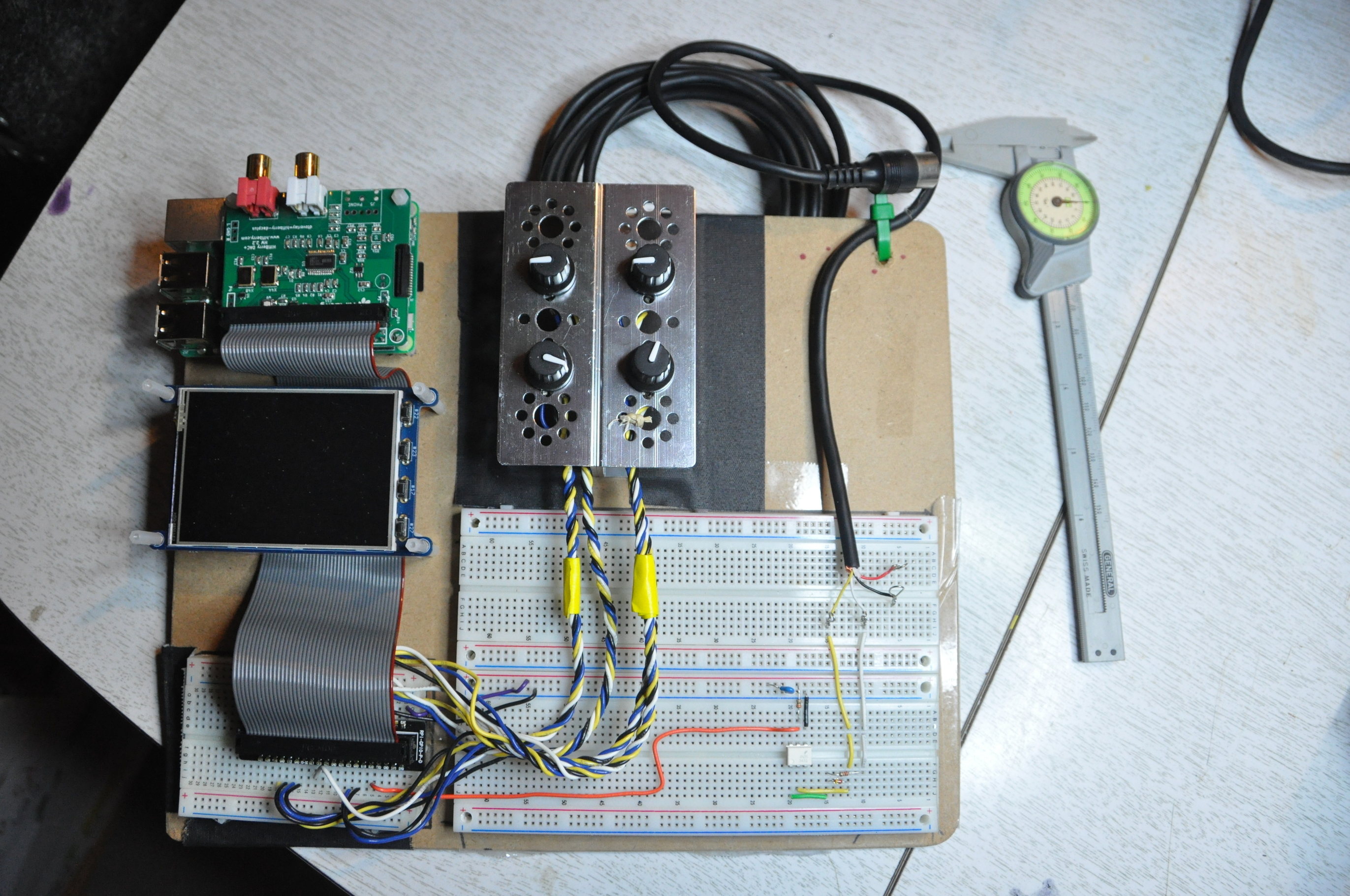
Here is a picture of my just completed zynthian build (calipers for scale.)
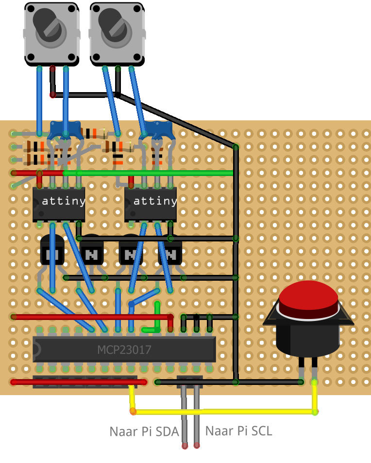
On the small protoboard are the connections to the GPIO pins.
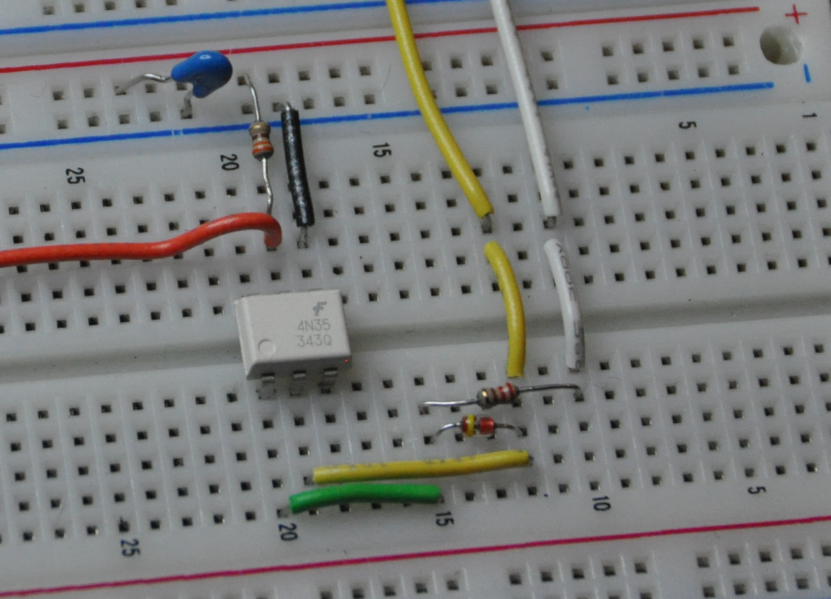
On the larger protoboard is the MIDI RxD interface hacked together from available parts.
Note the absence of the GPIO-ext (MCP23008 and related.) I found two unused GPIO signals on the rPi connector and referenced those in /zynthian/zynthian-ui/zynthian_gui.py rather than pins 7 and 8 on the GPIO-ext connector. More on that below.
The chief difficulties I met in building this:
- Small inconsistencies in the build docs. and lack of detail.
- Fritzing is no substitute for properly prepared schematics.
- There are at least two conventions for naming GPIO pins.
- Discovering usable GPIO signals.
- General unfamiliarity with rPi and wiringPi.
What follows is the “as built” documentation for this unit. I will be as complete as I can be in detailing the build. Including, calling out any differences from what I believe is the current canonical build. (Comments and corrections welcome.)
The Main Board
I used a Raspberry Pi 3 “Machine model: Raspberry Pi 3 Model B Rev 1.2” according to the kernel boot messages (dmesg | grep Rasp).
The SD image is zynthian_gorgona_rbpi3-2016-12-21.img.torrent (SHA1 37df1cdcea224f680e215b3e18ae28a99c3e9ca1) downloaded from http://blog.zynthian.org/download/.
Changes to the image according to the patch below.
The Audio Card
I used a HiFiBerry Pro DAC+ in the standard way. The audio card plugs into the rPi. I used the spacers that came with the audio card. I soldered a 20 pin connector to the top of the audio card. The ribbon cable plugs into the 20 pin connector.
The Ribbon Cable
I put a single male header facing up on the ribbon cable in between the existing male connectors that face down. The male header is for the display.
The Display
I used a 3.2 inch PiTFT from Adafruit (PiTFT Plus 320x240 3.2 TFT + Resistive Touchscreen : Adafruit Industries, Unique & fun DIY electronics and kits).
I have the buttons soldered to it, but they play no role. The display plugs into the male header in the middle of the ribbon cable.
This is a variation on the canonical build where the display plugs into a 26 pin header split off at the end of the cable.
The GPIO Connections
I used an adafruit breakout header (Assembled Pi Cobbler Plus - Breakout Cable [for Pi B+/A+/Pi 2/Pi 3/Pi 4] : Adafruit Industries, Unique & fun DIY electronics and kits) to connect the ribbon cable to the small proto board. This is a variation from the canonical build where individual GPIO connections are made to a male header installed on the ribbon cable. I prefer to use this protoboard since I anticipate that in the next iteration I will make the GPIO to encoder connections using a circuit board designed for the purpose.
The GPIO connections for this build are detailed on the schematics and will be discussed below.
The Encoders
I soldered wires directly to the encoder pins. The schematics mention some boards for the encoders. This anticipates a future build. I used the adafruit encoders (Rotary Encoder + Extras : Adafruit Industries, Unique & fun DIY electronics and kits).
The clever bit about the (future) boards is the wiring assignments. The encoders can be mounted on either the front or the back of the board depending on the encoder polarity. Similar to information hiding in object programming, this makes the encoder details private to the encoder assembly. The public interface is the colored wires which always connect in the same way to the rest of the machine.
The design of the encoder boards is a deviation from the canonical build. The wiring assignments and color code are also deviations.
The MIDI Input
This was hacked together from parts on hand. It is similar to the circuit on the 2in1 board but uses different IC circuits and discrete part values. The next build will likely use a different circuit.
I did not have a MIDI connector so I simply cut the end off a MIDI cable and connected to that directly. This means my circuit has a long tail. This is inconvenient, and I will change it in the near future.
The Final Result
The build was a success. When I plug the MIDI connector into the MIDI out of my ancient Roland S-10 I can play with sounds from the zynthian. My entire setup is as follows:
- S-10 keyboard MIDI out ---> zynthian
- zynthian audio out ---> mixer (Mackie 1202-VLZ3)
- mixer ---> amp (Fender Princeton Chorus stereo effects return)
- mixer ---> headphones
Mostly I use the headphones.
Now I will talk about what is on the schematic diagrams.
Encoder Schematic
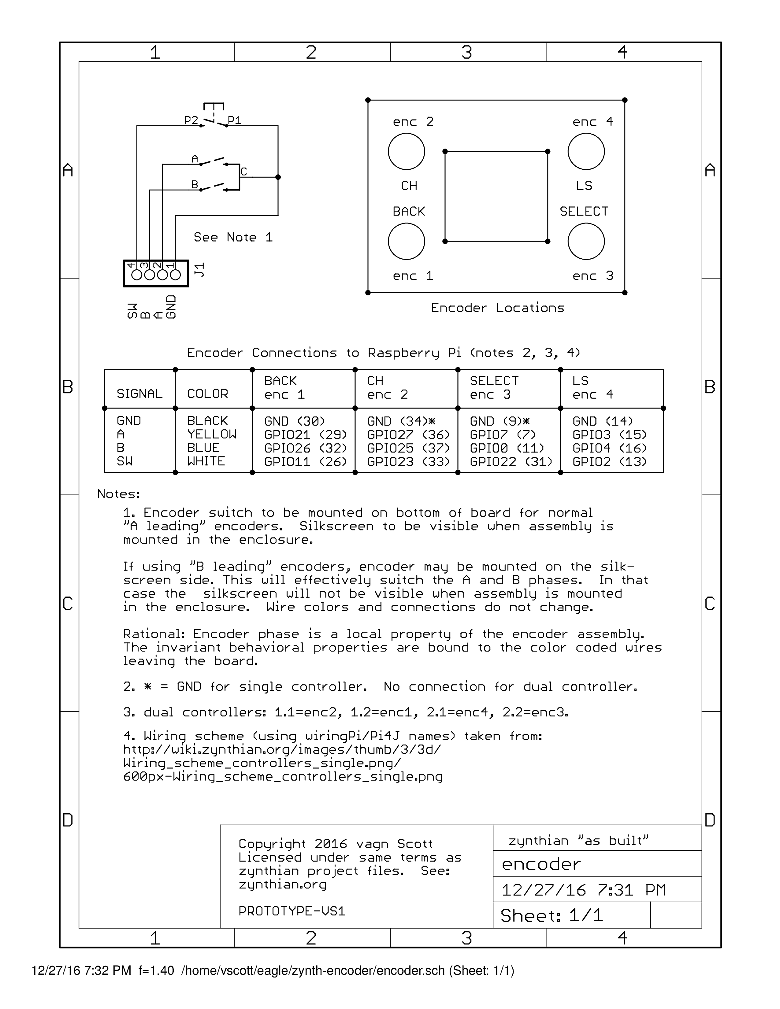
At A1 we have the encoder circuit. It consists of three switches that make connections to a common GND. The signals from the switches are A, B and SW. The circuit is arranged so that if the encoder is mounted on the back of the circuit board the A and B signals are reversed. This is what Note 1 on the schematic talks about.
A task for the future is to compile a table of encoders and their polarity. We should be able to build encoder assemblies that encapsulate the differences in encoder design such that the differences have no consequences for the use of the assembly.
At A3 is a diagram of where the encoders mount. The diagram also assigns names to the encoders (enc 1 through enc 4). The lack of consistency in naming (or perhaps the non-obviousness of it) was one thing that I had difficulty with during the build.
At B1 is a table that ties together the encoder assemblies, the colors of the wires from the encoder assemblies, the signals from the encoder assemblies, the encoder function (knob labels), and what GPIO signal they are attached to.
This table departs from the canonical build in the following:
- wire colors
- the use of GPIO11 and GPIO22 instead of GPIO-ext-8 and GPIO-ext-7.
- the need for a patch to the image (see patch below.)
Notes 2 and 3 discuss the mapping of this arrangement onto the dual controller board of the canonical build.
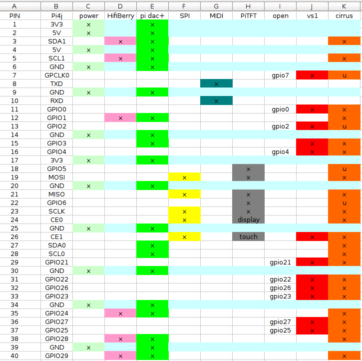
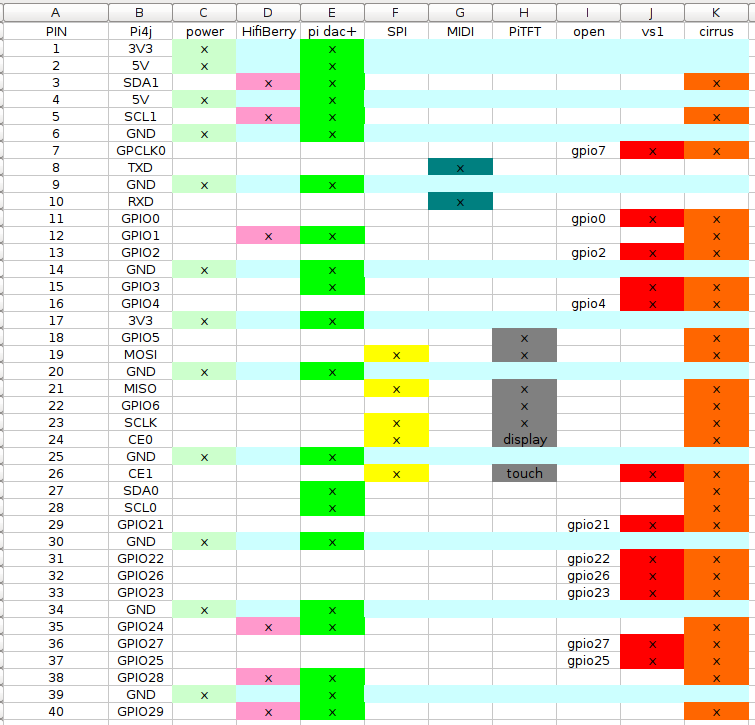
Note 4 mentions that the signal names follow the conventions of the wiringPi/Pi4J project. This is a critical point to keep in mind when reading the zynthian documentation. I started the build with the “element14” naming in mind and it led to no end of confusion.
Harness Schematic
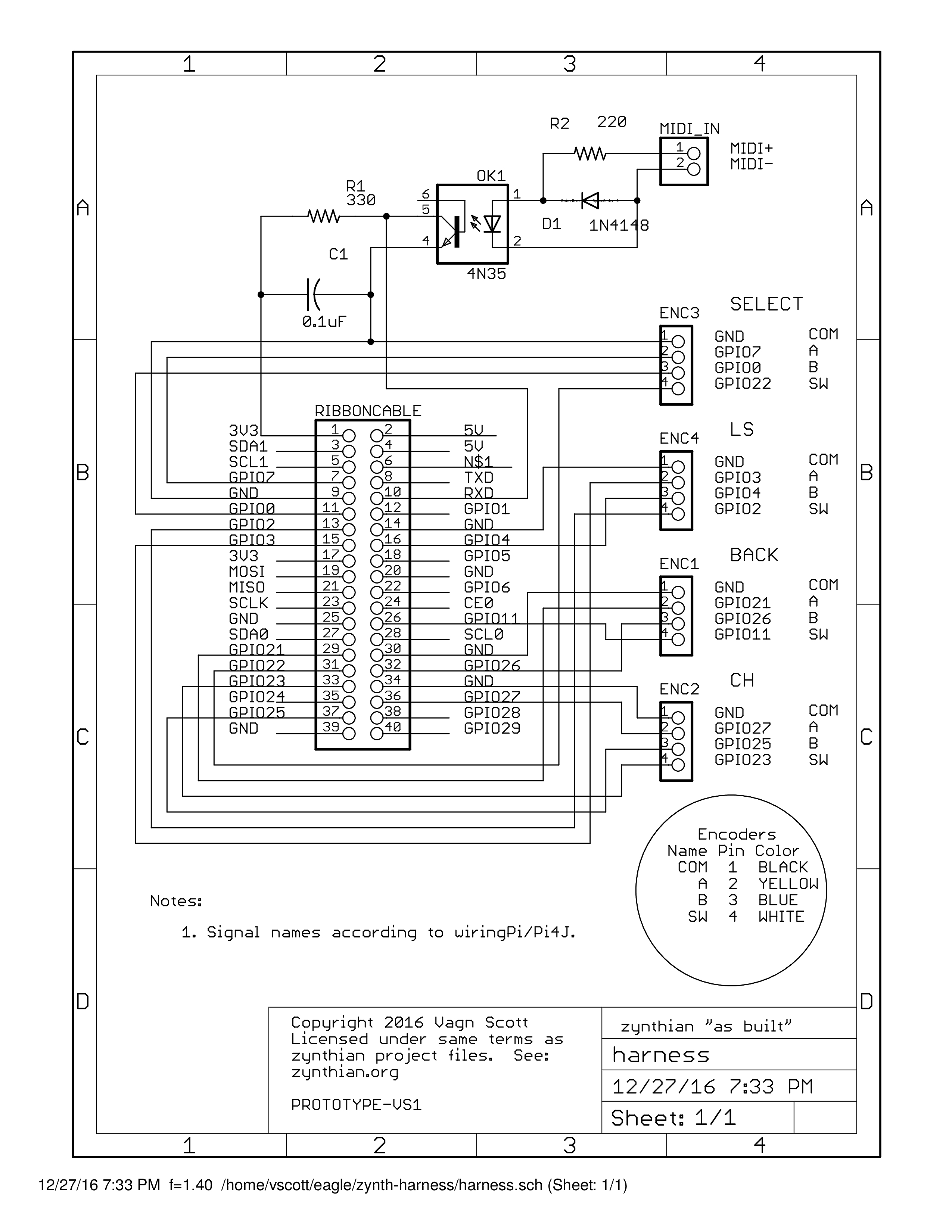
At A2 we have the MIDI input circuit. This is not interesting except to say that it works. It deviates from the canonical build in choice of parts and part values. But otherwise it is the same.
The rest of the diagram is dedicated to showing the connections between the GPIO pins of the rPi, encoder signals, signal names, wire colors, and encoder assembly names.
Future Work
Everything that is on protoboards in this build (GPIO connections, MIDI input) will be on a dedicated circuit board at the end of the ribbon cable in my next build. I think there is room in the box for that. If not, the box can get bigger.
I don’t like using a lot of connectors. The encoder wires will be soldered at both ends and twisted together over their length. I will keep the ribbon cable. But the discrete wiring will all be soldered directly to a “jungle board” that makes the connection to the ribbon cable. No more “plate of spaghetti.” (Exceptions: The MIDI Connections, and maybe power/battery input.)
I didn’t use the mcp23008 in this build because I didn’t have one on hand. And, had I orderd one, it would have arrived too late. (This build took place over the Christmas break.) This led me down the rabbit hole of finding some available GPIO pins. Also, I had to learn how the GPIO pins are handled by the software.
That led me to look at what GPIO pins are used by the audio card. And I realized that there is no standard for this. The next audio board I choose will likely use a different set of GPIO pins than those the HiFiBerry Pro DAC+ uses.
If we want a robust design we must stay off of the GPIO pins entirely. Which is to say that, unlike this build, which sought to avoid the use of GPIO-ext pins, we should go all the way and put every encoder signal on the GPIO-ext. We need more pins on the GPIO-ext. This means using a mcp23017 or mcp23s17 instead of the mcp23008.
I am thinking of including a power backfeed circuit as well. This would use the rPi recommended 0v protection circuit on the 5v downstream from a nice stiff 5v buck/boost converter. It would also give us a way to power the box from batteries.
I think the current USB power supply is inadequate and likely responsible for some the reports of clicks and other strange behaviour (I have seen uncommanded reboots, for example.)
On the topic of auto-configuration based on eeprom data: The rPi HAT spec doesn’t allow for cascaded configurations. Because the audio card already has a config eeprom on it there is no possibility for accessing another eeprom to pick up the zynthian hardware configuration details. The only solution there is to design our own audio circuit. From there we can do whatever we want regarding the devices attached to the ribbon cable. That may be too much, though.
Well, one step at a time.
If there are errors or omissions in this report please call them out and I will address them.
Thank you to all for a great project!
The patch file:
— /zynthian/zynthian-ui/zynthian_gui_config.py-saved 2016-12-26 05:21:38.162831275 +0000
+++ /zynthian/zynthian-ui/zynthian_gui_config.py 2016-12-28 00:46:27.296328104 +0000
@@ -33,7 +33,7 @@
raise_exceptions=False
Wiring layout
-hw_version=“PROTOTYPE-4”
+hw_version=“PROTOTYPE-VS1”
Screen Size
width=320
— /zynthian/zynthian-ui/zynthian_gui.py-saved 2016-12-26 05:45:26.782830730 +0000
+++ /zynthian/zynthian-ui/zynthian_gui.py 2016-12-28 00:46:39.856328114 +0000
@@ -135,8 +135,13 @@
Wiring layout => GPIO pin assignment (wiringPi numbering)
#-------------------------------------------------------------------------------
+if hw_version==“PROTOTYPE-VS1”:
-
zyncoder_pin_a=[25,26,4,0] -
zyncoder_pin_b=[27,21,3,7] -
zynswitch_pin=[23,11,2,22] -
select_ctrl=3
First Prototype => Generic Plastic Case
-if hw_version==“PROTOTYPE-1”:
+elif hw_version==“PROTOTYPE-1”:
zyncoder_pin_a=[27,21,3,7]
zyncoder_pin_b=[25,26,4,0]
zynswitch_pin=[23,None,2,None]

