Matching the zynaptik is really the way to go.
This is an open source hardware project so there are no hidden eproms or other such lock ins at work.
To be honest this is an excercsie in the early days, more of soldering than anything else.
First make sure you can talk to the 23017. To do this you use the command line
i2cdetect -y 1
(venv) root@zynthian-rack6:~# i2cdetect -y 1
0 1 2 3 4 5 6 7 8 9 a b c d e f
00: – – – – – – – –
10: – – – – – – – – – – – – – – – –
20: 20 – – – – – – – – – – – – – – –
30: – – – – – – – – – – – – – – – –
40: – – – – – – – – – – – – – – – –
50: – – – – – – – – – – – – – – – –
60: – – – – – – – – – – – – – – – –
70: – – – – – – – –
(venv) root@zynthian-rack6:~#
This is from the unit I phot’d up above ( rack6 to the train spotters amongst us)
It show’s the address the 23017 is registering which in the case of the zynaptik is select-able on the board with a bit of soldering.
To 20 …
There’s no point in proceeding any further down the ribbon cables till you get this bit working.
Because this is the first step in the chain.
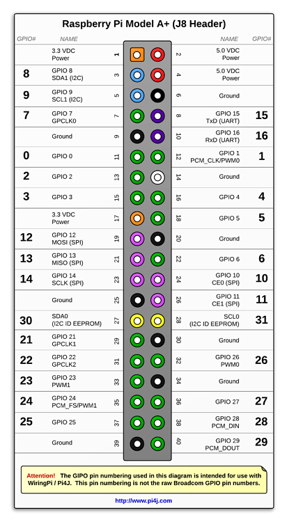
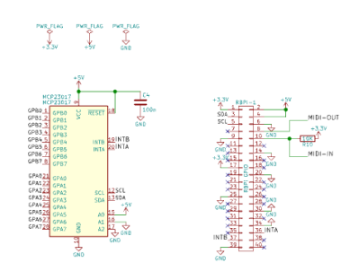
You need the i2c connection on the Pi and the two Interrupts. To cut a long story short, you can either have the zynth take regular looks at your 23017 and check for change, or have the edge of consiousness, 23017, do this and attracts the attention of the Pi that it has something worth saying.
So we have two different Interrupt stories to tell in zynth world.
Someone might even mention what they are . . .
Transfering this bit of front end GUI interoperability out to a bit of dumb hardware ( sorry, 23017) is precisely the way to get a little bit more audio doing goodery out of a Pi.
That’s probably your best reason for going non GPIO.
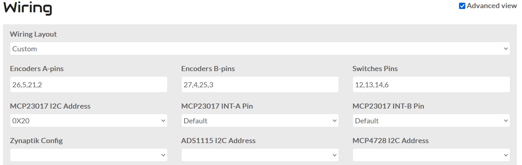
Have a look at the config page for the wiring when in custom mode and see how it starts to line up.
So get your 23017 saying 20, and think about how it is to all be ruggedly mounted