I agree with you @stojos … you made the same journey as me… I built myself some radios with which I spoke to the World, but IT is another thing and I had many doubts…
You’re probably right. I cannot read schematics, and I did not touch neither a Pi nor any electronic component in my life. But I do understand your intention and I appreciate that.
Otherwise we are all standing on shoulders of giants (or whatever that saying was). If I can manage to get working what I planned, I’m happy. In the end I want a working thing, and learning things on the way is a nice to have.
My last journey to such an unknown field was when I tried to get into audio plugin programming. People before me had to dive into vst sdk completely and had to stick to what Steinberg threw at them quite undocumented and had to make their dsp from dsp filter academic publications. I was lucky to just forget about crossplattform compatibility and the Steinberg SDK because frameworks already existed, and there were already some c++ dsp libraries to at least look at what others are doing. Now you can make plugins from a wysiwyg-editor just dragging rotary knobs on a canvas.
But yes, I’ll look at these schematics and try to get used to that.
Everyone has their own specializations… I met Zynthian because I just wanted to play an instrument…
The same thing happened with electronics… I became a Radio Amateur, but the spirit back then was: “Build a radio and then transmit”… Now it’s no longer like that… but how many things I’ve learned (and how many I’ve burned…). ![]()
2 Likes
It’s the electronics equivalent of music score.
Make what you will of that.
And.
You know far more than you realise, simply generated by your interest in the area.
It’s very easy to dismiss anything you don’t know as hard, and anything you do know as easy.
1 Like
From today @wyleu in addition to being the bell ringer of the Forum, will be elected “Philosopher ad honorem”. Deservedly. ![]()
1 Like
Looking at these schematics sounds like resolving G7 to Dmadd#11flat13 third inversion in my brain.

@hannesmenzel If you get this chord wrong, you don’t see the sparks and you don’t smell anything burning…
These 1.5 schematics I slowly unterstand, at least for the RPi to MCP23017 part. I might be even able meanwhile to abstract from the fact it is a RPi1 in that setting.
For the V5 control schematics, I don’t know, I only see renderings here. Do I need to get into these KiCad stuff? To quote Dolores Abernathy: “It doesn’t look like anything to me.”
I hesitate to disagree with @Lanfranco on the need for de-bouncing caps, but, I really think they are worth the (slight) extra cost and effort - without them your RPi is doing extra work to figure out what the encoders and-or switches are doing, and you never know when it will fail - often after you’ve forgotten all about this and you don’t get any clue what’s causing the odd misbehavior. My 2 cents worth of advice from the Peanut Gallery.
It’s another worthwhile time investment. Because if you build something you owe yourself ( and the universe) a description. Because, if you don’t when things develop, you end up having to go back and work it all out again from the start.
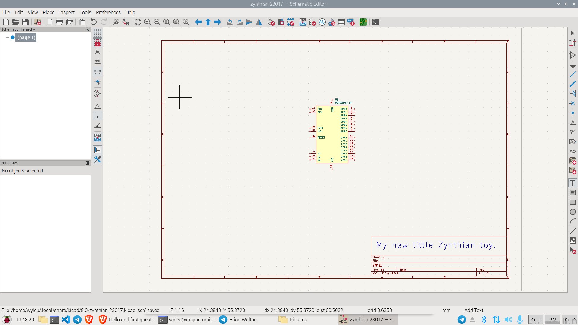
Kicad has a nice pre rolled 23017 to use. . . .
Best to learn to from a clean slate rather than modifying other schematics.
I think I’ll try this tonight. Note I’ll repead the connected caps for switch 2 to 4 accordingly.

As you can see I’m pretty proficient in MSPaint 1.0
2 Likes
zynthian-23017-toy.kicad_sch (28.9 KB)
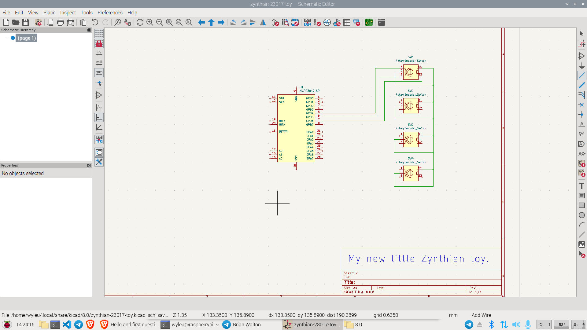
I don’t know your pin outs on your drawing but they can be easily adjusted.
Do you short the encoder + and - to GND?
No! Connect Gnd to Gnd and leave +V disconnected.
Indeed, but keep in mind that you want the caps to be mounted as close as possible to what they are de-bouncing with the shortest leads possible - long leads get in the way of they’re doing their function.
I intend to bend them from row “a” and “j” to their closest “-”, but that was not possible in Tinkercad
1 Like
Thanks, I thought so.
The first thing you want to test is the select switch on the encoder. This is the one that probably does the most work and is most obvious when getting going.
In the same way finding ic2detect -y 1 should show you you have i2c connection then this will allow you to see that zynthian is actually getting it’s most basic GUI command.
Course you could turn on the long press status branch and see the status mechanism work. Good for making sure the de-bounce is behaving !!!
But simply selecting something on an hdmi screen is confirmation and satisfaction enough!
Now it might seem clearer.
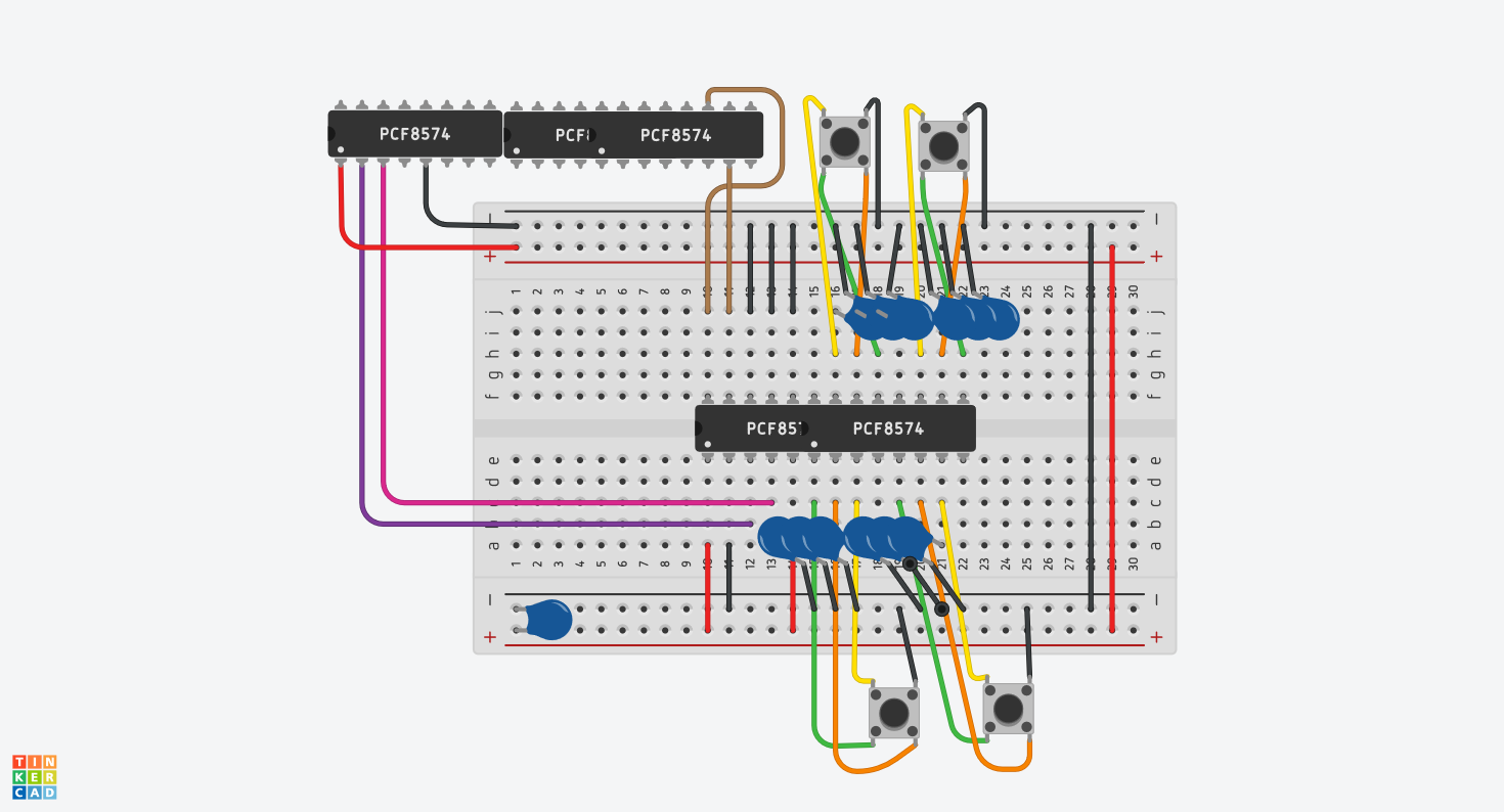
Sorry, I hope it is clear that the upper bunch of PCF8574 is actually the Pi GPIO and the thing in the middle the MCP23017.
Two questions left (again: newbee stuff):
- How do you even prototype with the MCP23017 and the provided pin headers. I mean, these do not really connect. Do I have to solder them already?
- The cap on the lower left side just connects between + and -. I saw in the schematics that there is a 100nF cap from Reset to GND. So while Reset is connected to 3.3V+ already, this seems appropriate to me.
1 Like